Modern Dining Table Part 3: The Conclusion

Part 1 and Part 2 here.

This weekend I wrapped up my modern dining room table project by installing the legs. Rather than 4 individual legs, I chose two trapezoid shaped metal frames on each end.

photo (16)

This table won’t have an apron, which gives rigidity to a table. Think of the point where the table attaches to the legs as a hinge. The further away from the hinge that the leg is supported the more rigid the connection, so apron = good, stretcher = better.

With a leg configuration like I have you’d normally need a stretcher between the legs to prevent the table from wobbling side to side.

Screen Shot 2013-10-06 at Oct 6 5.00.34 PM

How to make a stable table. able.

To eliminate the need for a stretcher, the flanges where the top connects to the legs were made extra wide by adding a piece of 3/16″ angle to the steel tubing.  1/4″ lag bolts secure the legs to the top (pre-drill so you don’t split the wood!)

P1010785

I wanted some contrast between the legs and the warm natural look of the reclaimed wood table top. Rather than paint the legs I had them clear coated, allowing the welds and tube seams to show through.

P1010791 P1010793

I need to put some felt pads under the legs to protect the floor, but other than that I’m going to call this one done.

Suppliers:

Wood table top: http://www.americanmaad.com/tables

Legs: http://www.etsy.com/shop/TRRTRY

Advertisement

Sealing it

With the melt tank installed and the pump body assembled, I can now start fitting the injection cylinder to the tank. The large (50mm!) air cylinder moves a piston in the pump body to draw in molten plastic, and then force it into the mold cavity. The piston seals to the pump body with a cup seal. The original mold-a-rama actually has no seal on the piston itself, it seals around the shaft of the injection cylinder, the seal can be seen here:

DSCF5337

This is the injection ram of the mold-a-rama. The seal is in the center of the picture on the aluminum plate, the fiberglass insulation is covering the tank.

Installing the seal was a real bear. The cup seal is sized for a 3″ cylinder, it flares out to ~3.25″ OD to press against the cylinder walls. I needed to compress is to fit it into the cylinder. Softening the seal really had no impact on it’s flexibility, what I really needed was a piston ring compressor. Lacking that I used several daisy chained cable ties. That still didn’t work well so I used some plastic tools to push the seal in.

IMG_0290

I wasn’t sure what to use to insulate the melt tank until a fateful trip to Lowes. In the pipe insulation section I found this self-adhesive aluminum foil backed foam tape. The adhesive holds up to the tank temperatures, and the heat radiating off the tank is noticeable reduced (as measured using the calibrated portion of the back of my hand).

IMG_0292

I looked long and hard for a plastic water tank that was compact, but had a large enough opening to fit the water pump through. The water pump is supposed to be submerged in the water tank, this  will extend the pump life by keeping it cooler. I gave up on finding a plastic tank and made a metal one myself. The body is made from 6″x6″x.120″ wall aluminum tubing with a water jet aluminum flange and lid. A cable gland seals around the power cable. The gold cylinders sticking out from the flange are rivnuts, those along with thumb screws will allow tool-less removal of the water tank  lid for refills. I plan to add a sight glass later on so I can check the water level with out removing the lid.

IMG_0712

The mount for the mold delivery cylinder (the one that pushes the finished plastic part into the retrieval bin) is made from a small piece of 1″x3″ aluminum tubing welded to the top frame and a shaft collar.

IMG_0713

The lower half of the aluminum shaft collar is welded to the back of the rectangular tubing, the upper half is free  and is what clamps onto the cylinder.

IMG_0714

The molder is pretty awkward to move around as it doesn’t sit on a wheeled base. I added handles to each side to make moving it a little easier. The first set of handles I got from McMaster were plastic, thinking the machine couldn’t weight more than 100-150lbs, it turns out I forgot to take into account two very heavy items: the water chiller and the compressor. After putting those in, the machine weights closer to 200lbs. The plastic handles were quickly swapped out for some beefy aluminum ones. I’ll still probably move the machine with the compressor and chiller removed, but now I have a lot move confidence in the handles while moving the machine.

IMG_0717

And finally, before I go, a sneak peak of the new molds!

IMG_0725

Light Assembly

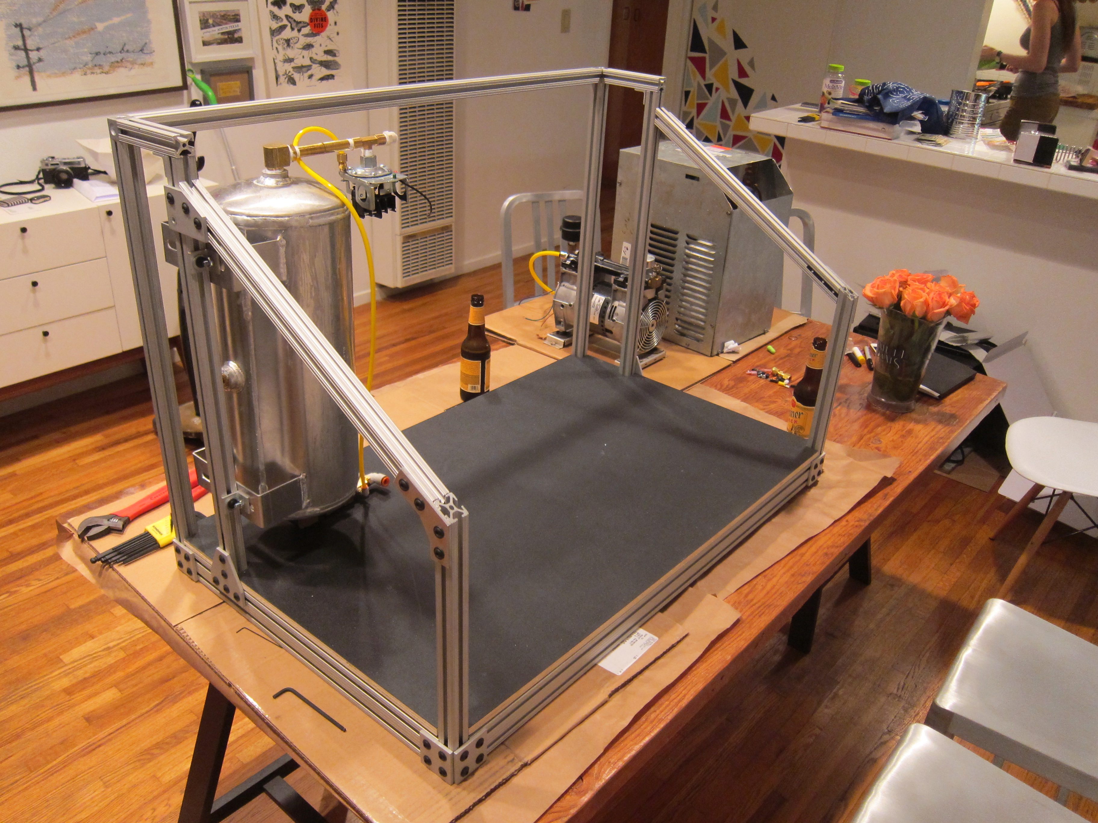
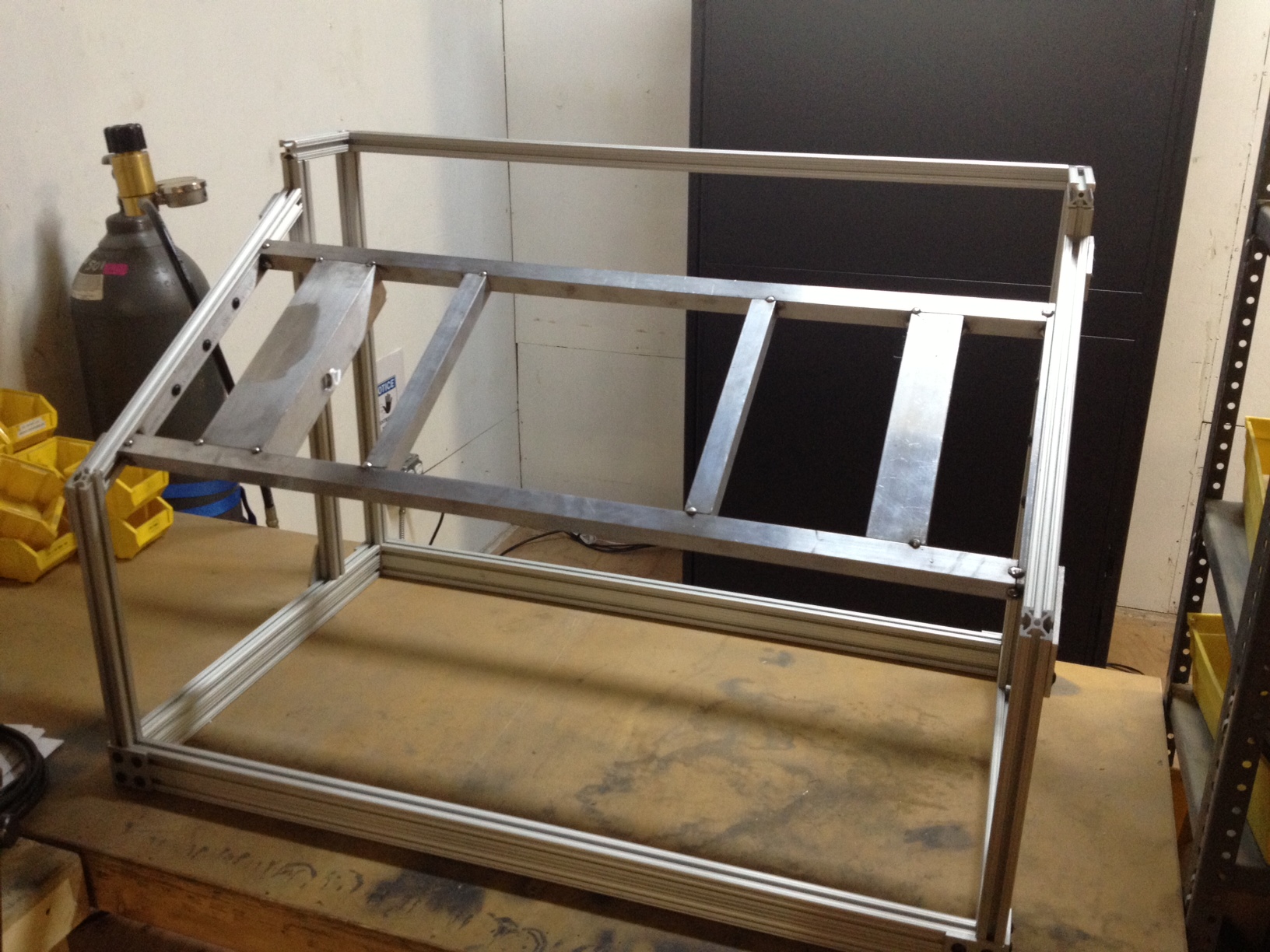
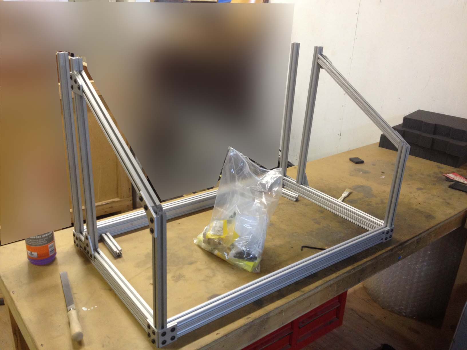
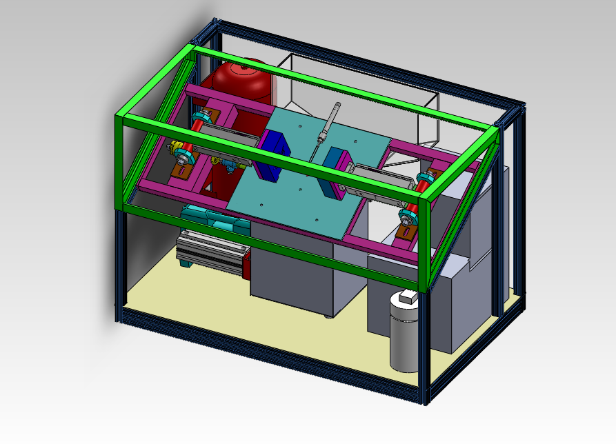
Things really started to come together this week. After spending a solid month machining, cutting, tapping, and welding parts and sub-assemblies, I began putting it all inside that empty 80/20 frame.

The air tank went in first. I am not completely happy with the mounting method, but it’s good enough for now, I’ll most likely make some bent brackets for it later on. The black board on the bottom is 1/2″ plywood laminated to a thin ABS sheet. It’s cheaper than solid plastic sheet and it gives it a finished look.

IMG_0279

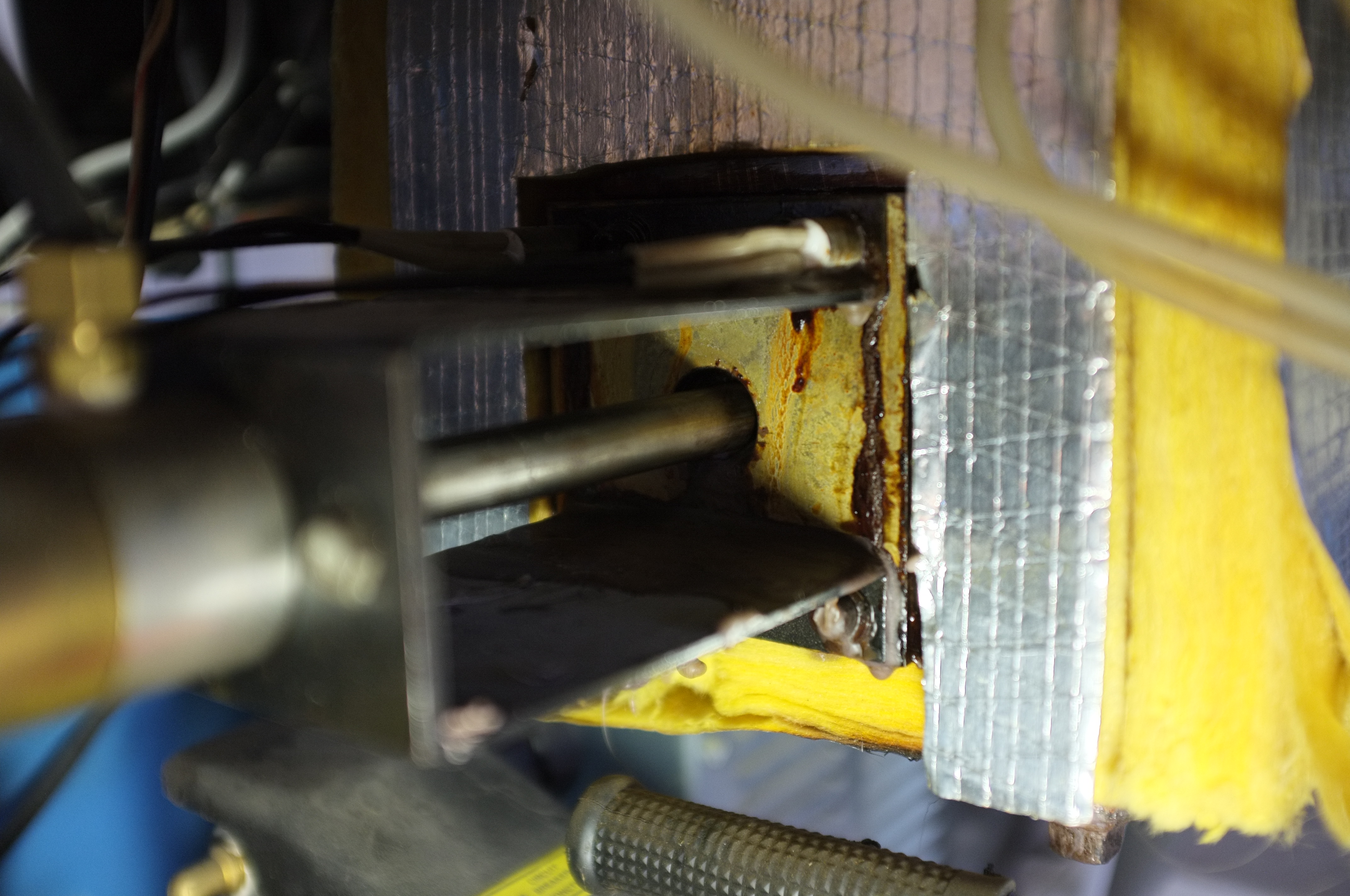
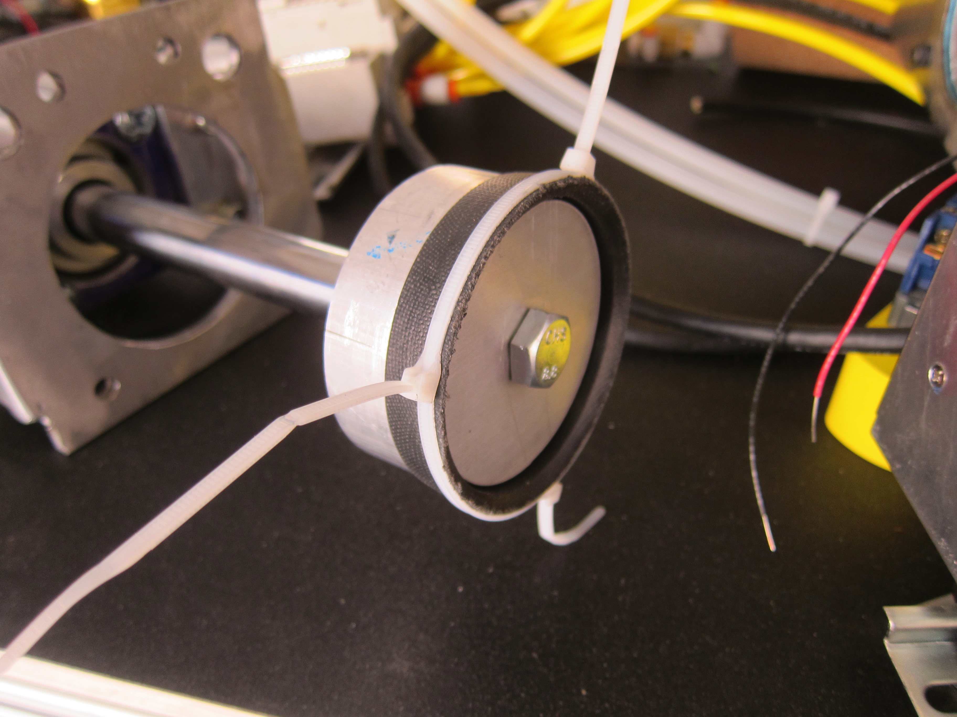
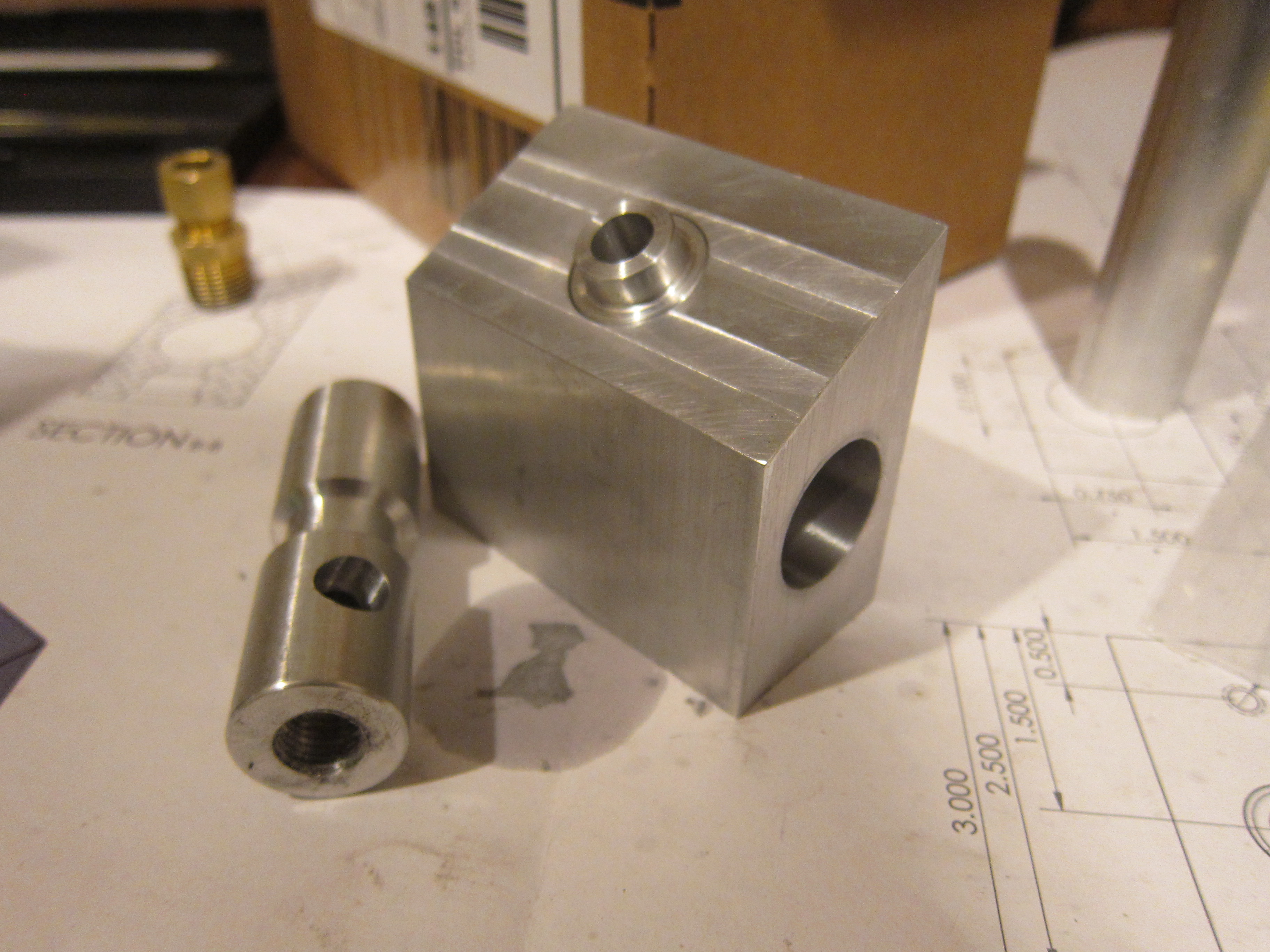
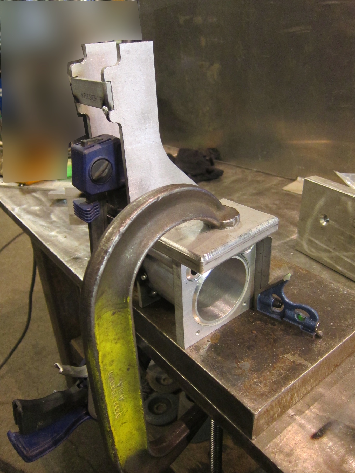
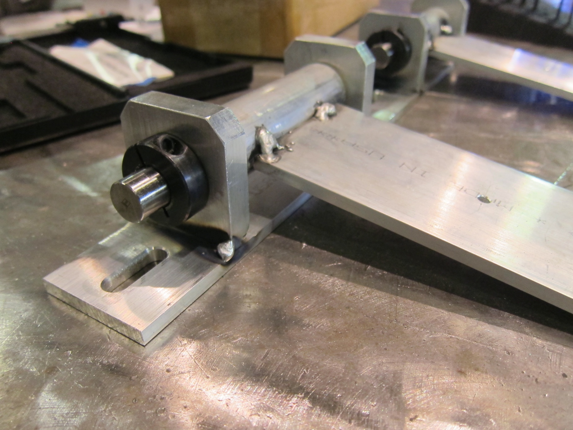
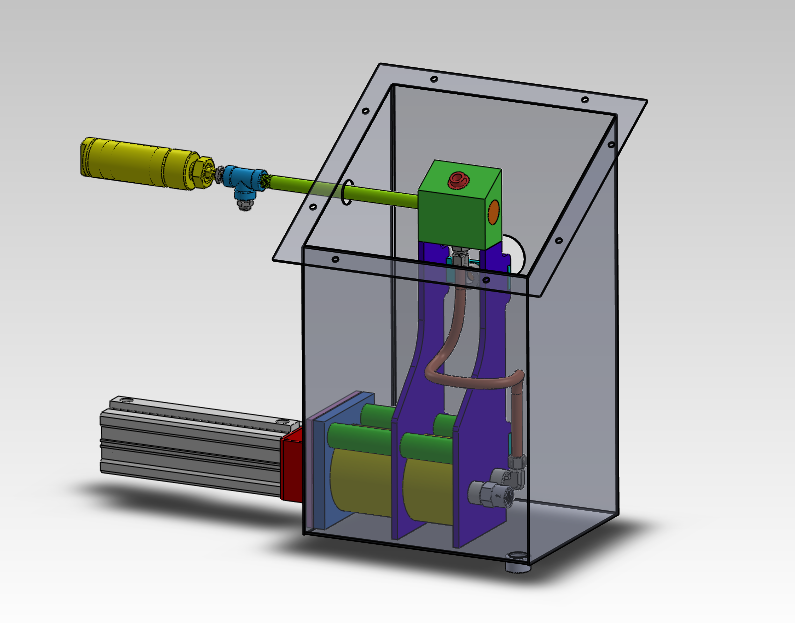
I started assembly of the pump body next. The pump body sits inside a tank of plastic material. It serves several functions. Cartridge heaters slide into the smaller 1″ OD x 0.25″ wall aluminum tubing, heating the entire weldment, and thus melting the plastic around it. The larger tube is the pump cylinder, inside that is a piston with a cup seal. When that piston is pulled back, it sucks molten plastic into the pump via the check valve (the cylindrical brass fitting). When the piston extends it forces molten plastic up the copper tube and into the valve body up top. It’s basically a 3″ aluminum syringe.

In the real mold-a-rama this is a one piece casting (it also doesn’t use the check valve). Since I don’t have access to an aluminum foundry, making it from plate and tube was the next best option.

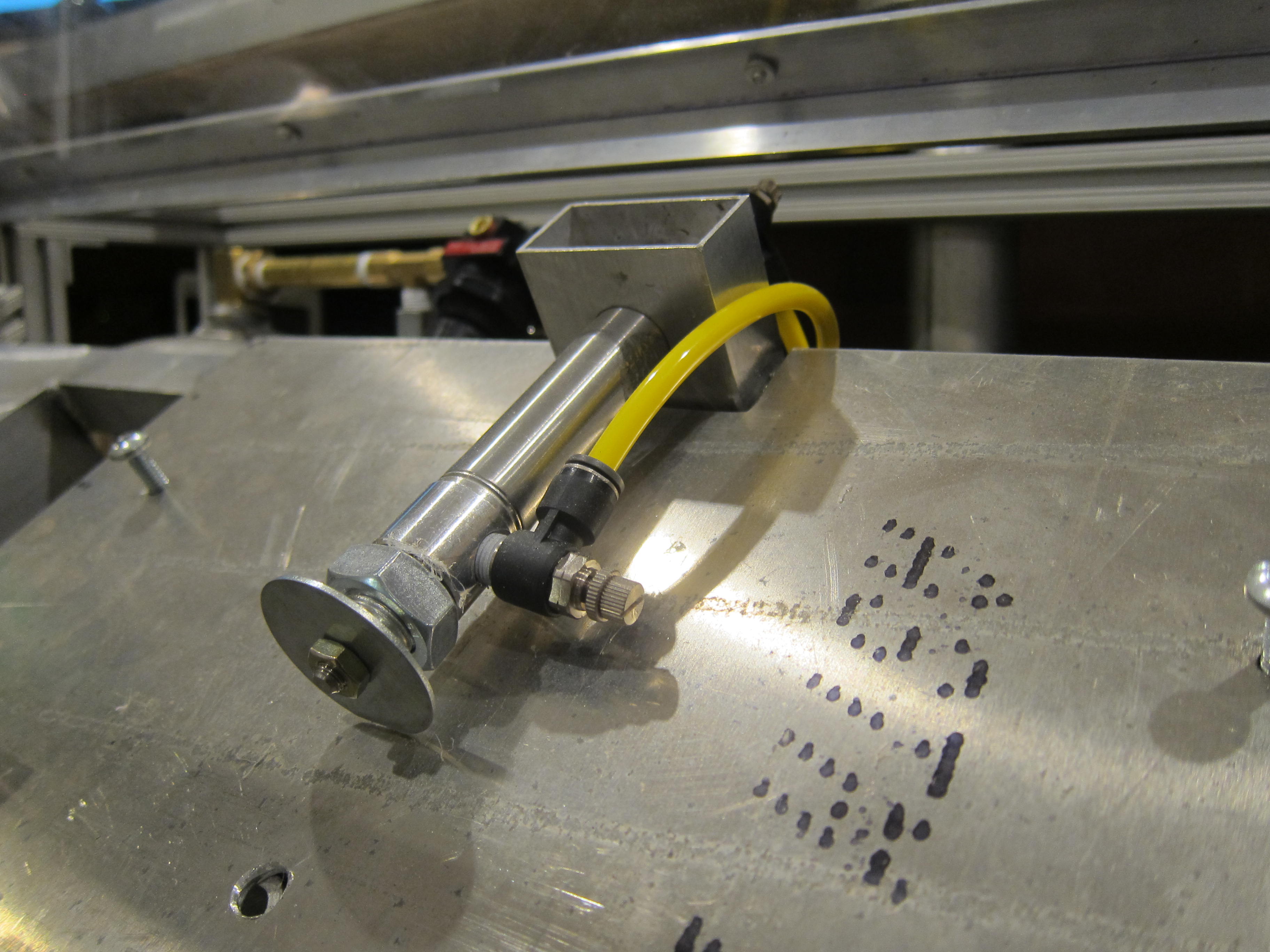
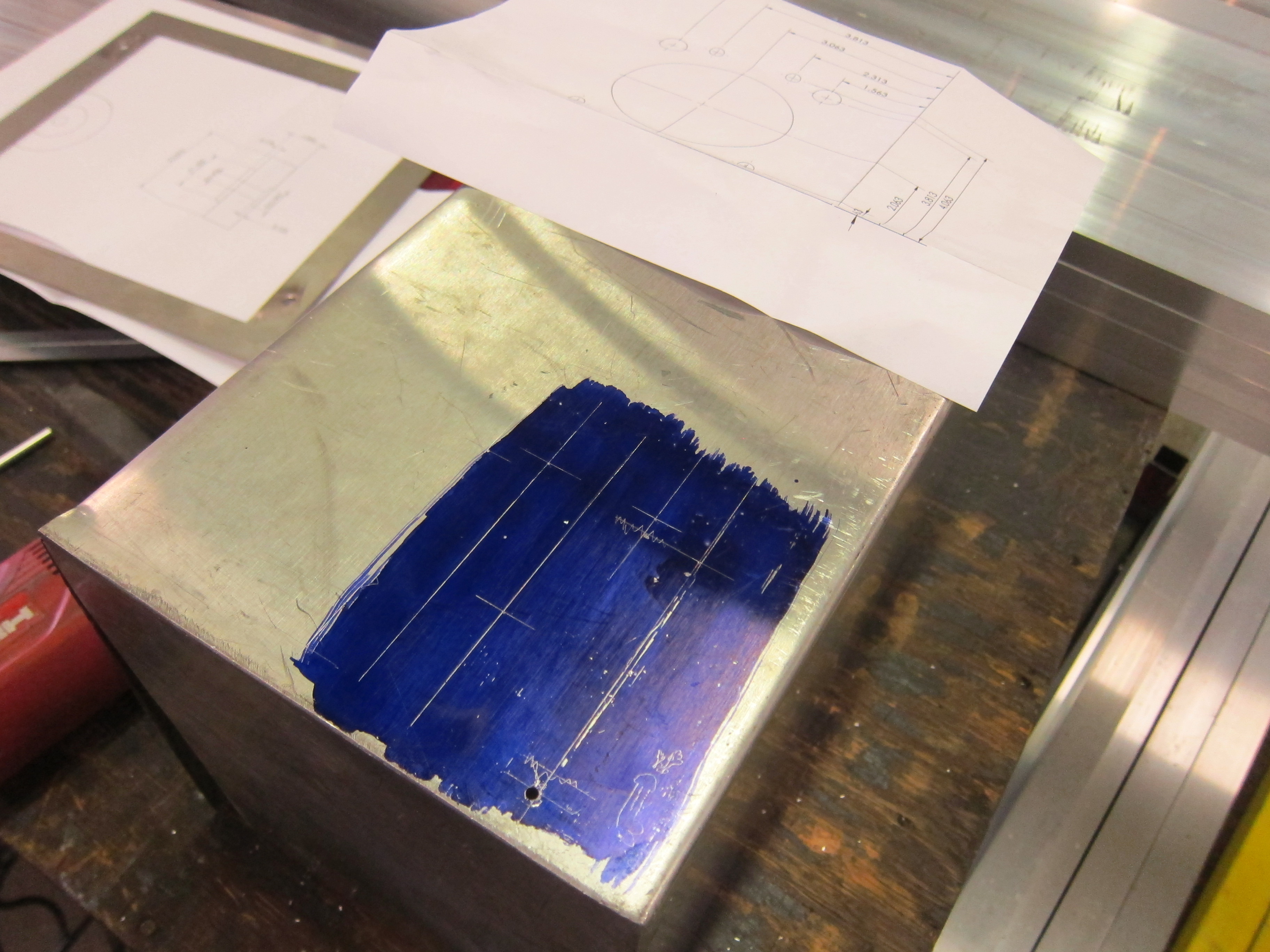
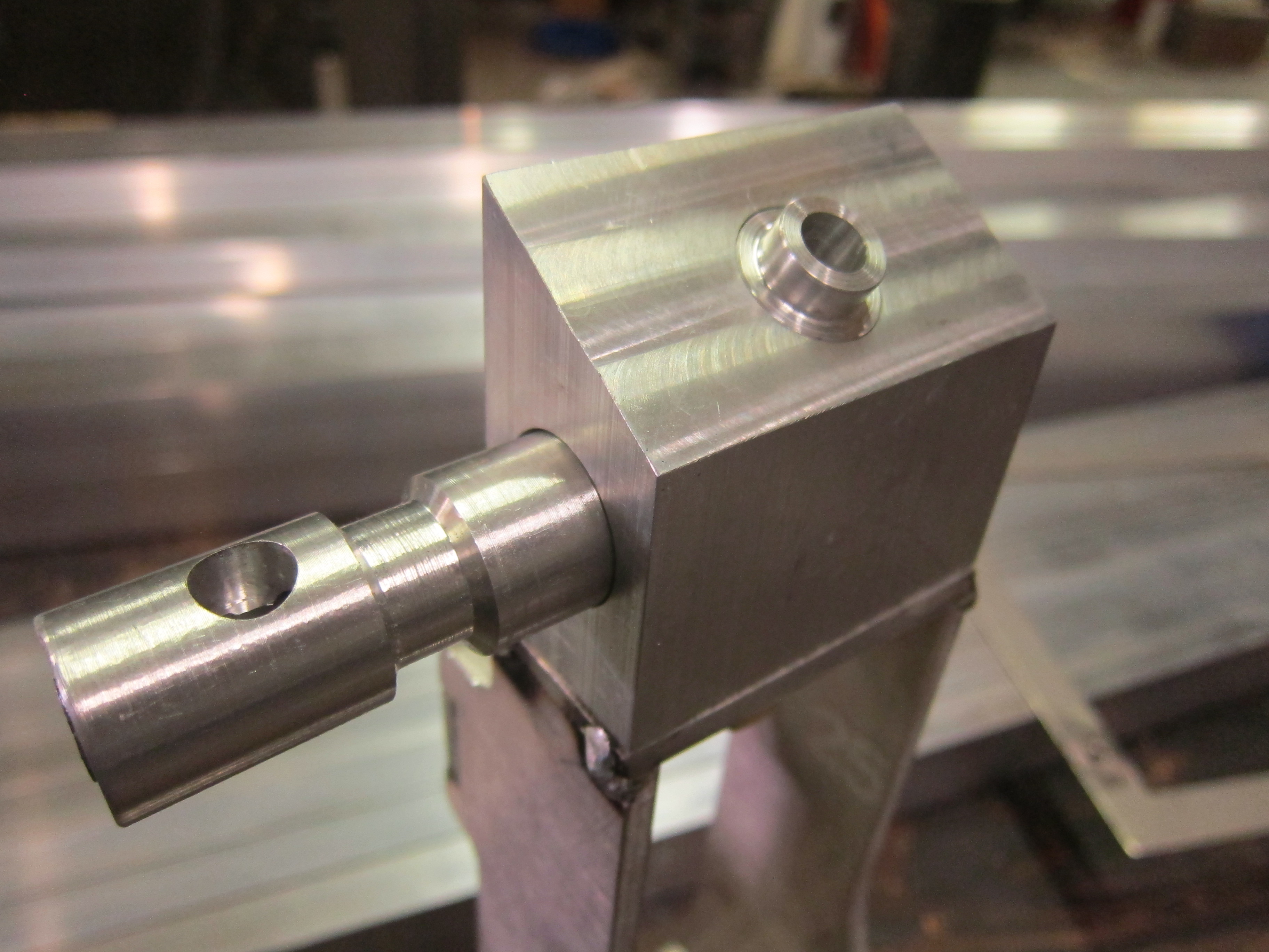
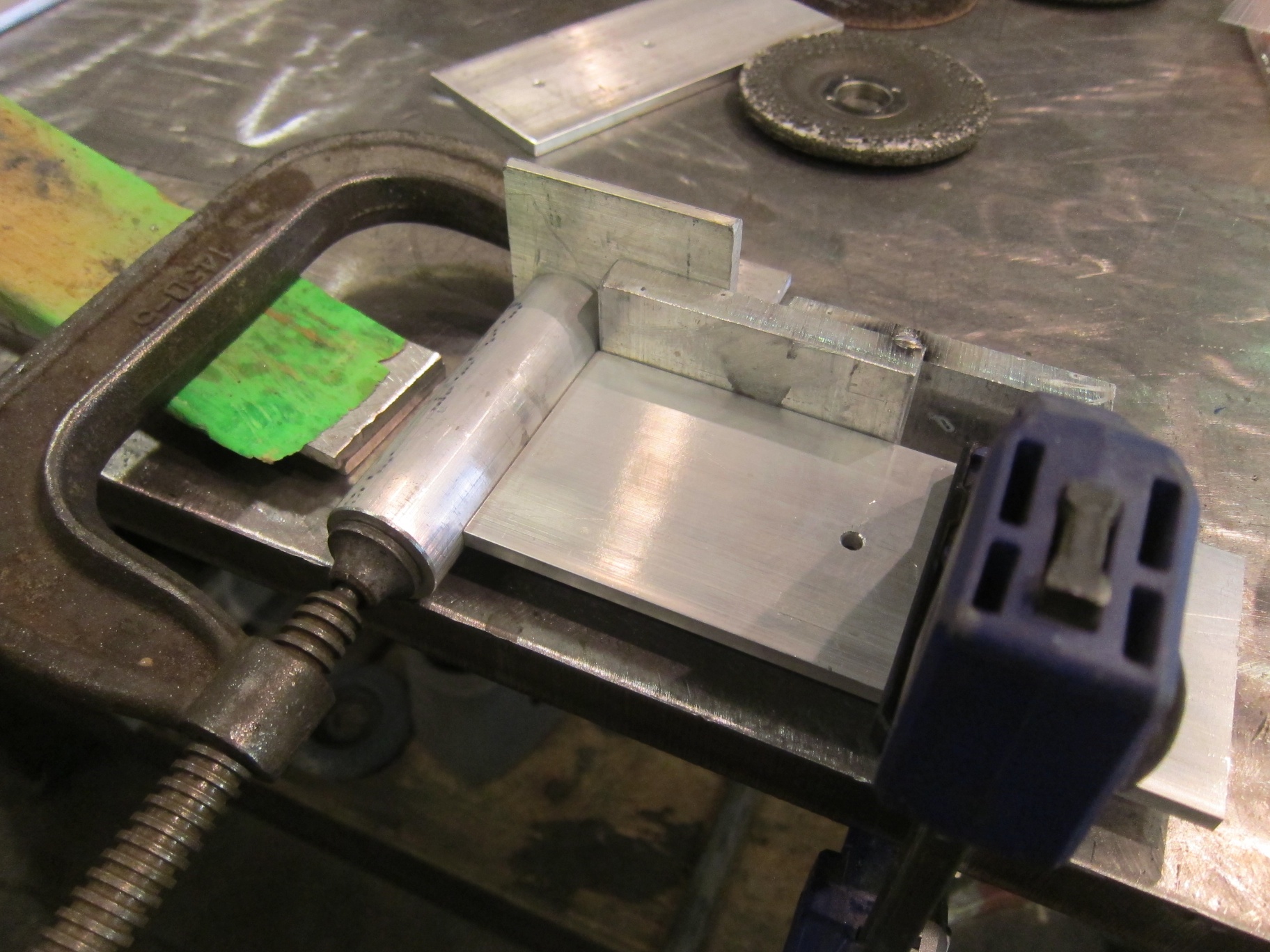
I started with the base weldment and added the valve body on top and fittings on the side.

IMG_0280 IMG_0281

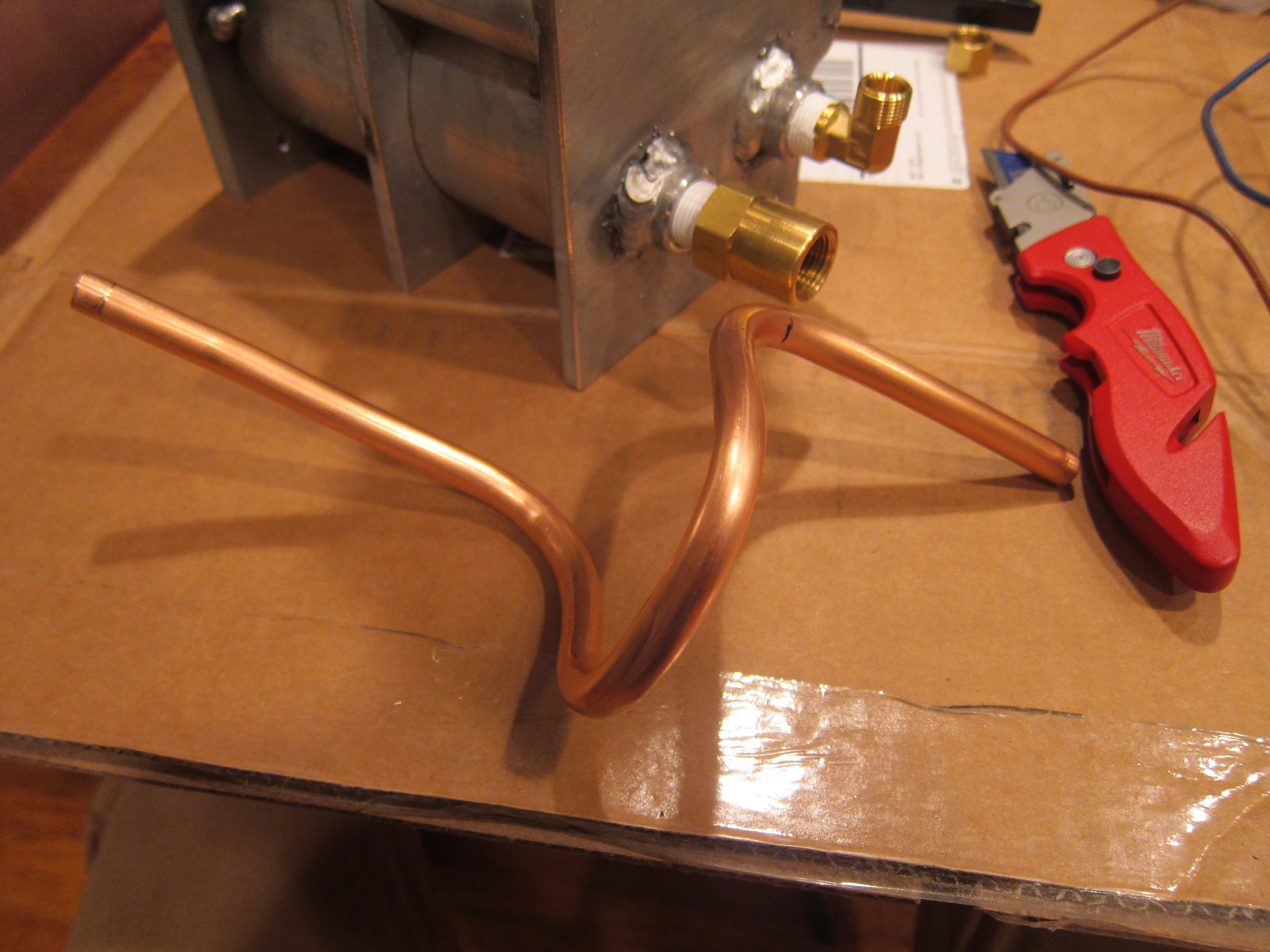
Next I bent up a piece of soft copper tubing. Side note: during manufacturing, drawing the copper to size work hardens it making it very hard, annealing it brings back it’s ductility (soft and bendy), if you accidentally buy hard copper you will not be bending it without splitting it open.

Also make sure you buy the correct size copper tube. Copper tubing is sold both in 3/8″ ID and 3/8″ OD sizes. The brass fittings are 3/8″ compression type and are meant for 3/8″ OD tubing.

IMG_0282


I thought bending the tube was going to be really tough, as I have two distinct points I need to reach, so the copper needs to be bent within ~1/16″  the correct dims, otherwise it won’t sit correctly in the fittings. I made some careful measurements, bent in increments, and left myself some extra length on the ends to trim to size. Surprisingly I got it right on the first attempt.


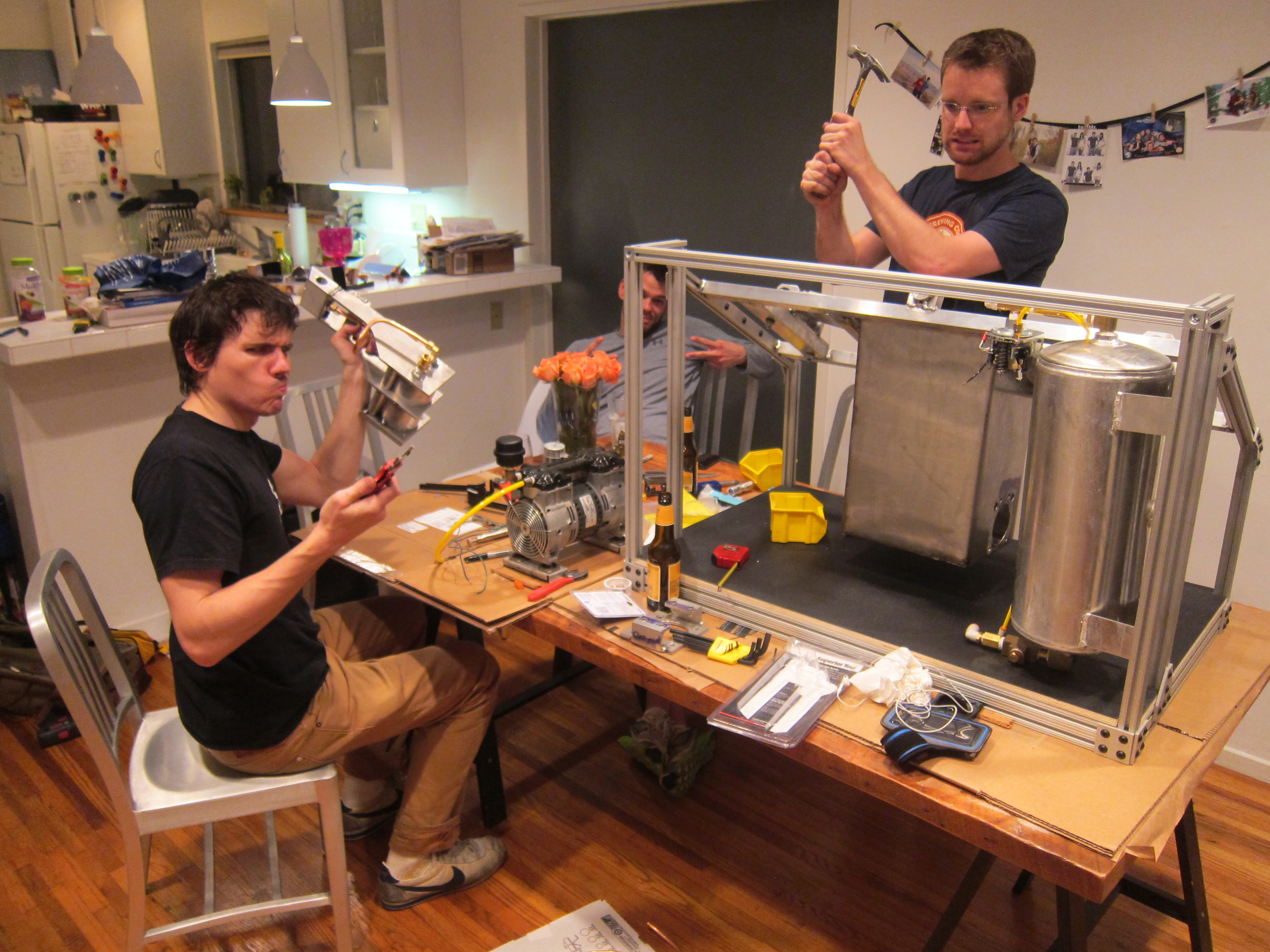
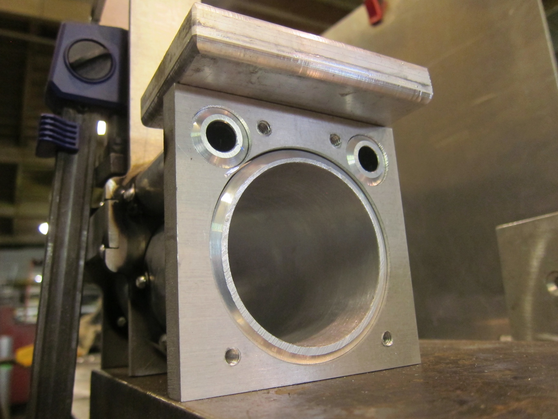
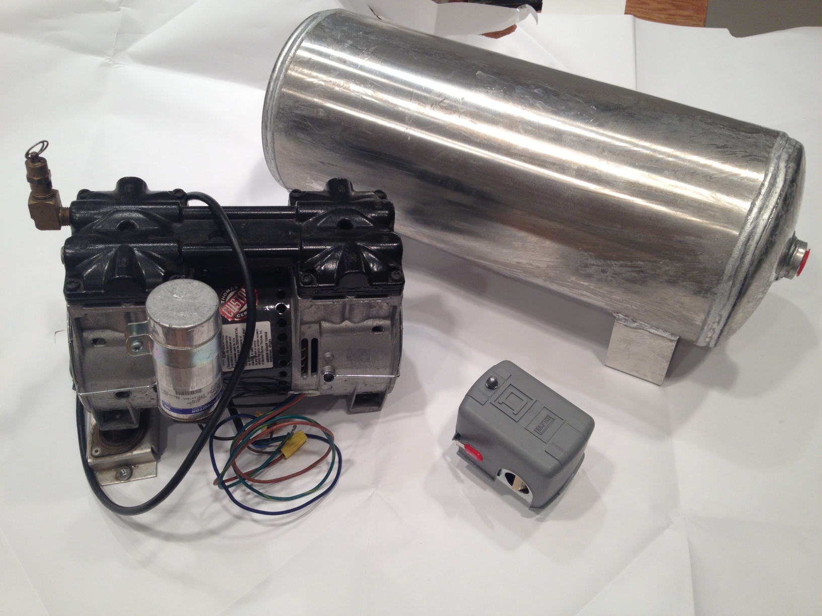
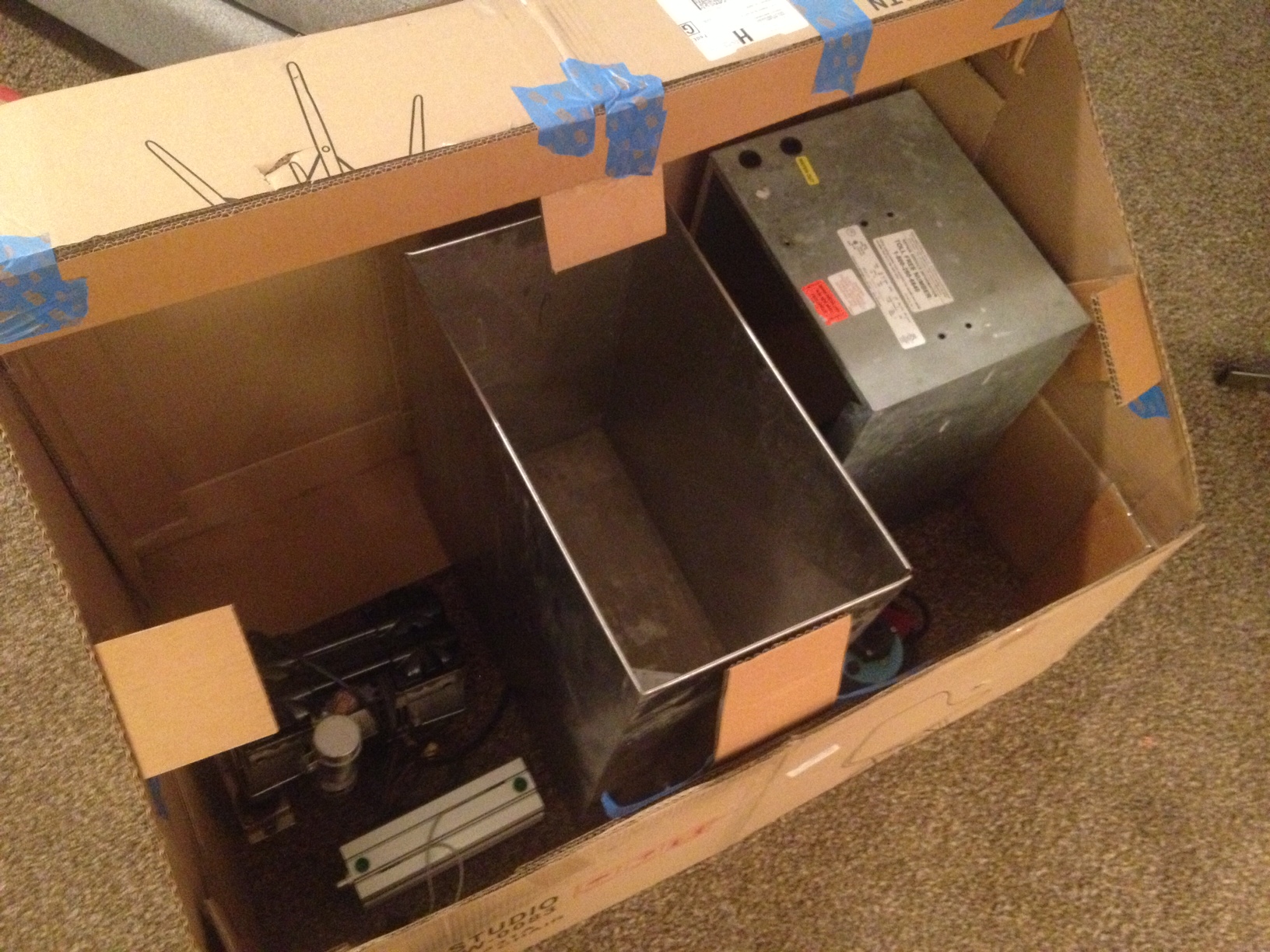
Unfortunately the only picture I have of the completed pump body is in this awesome photo:
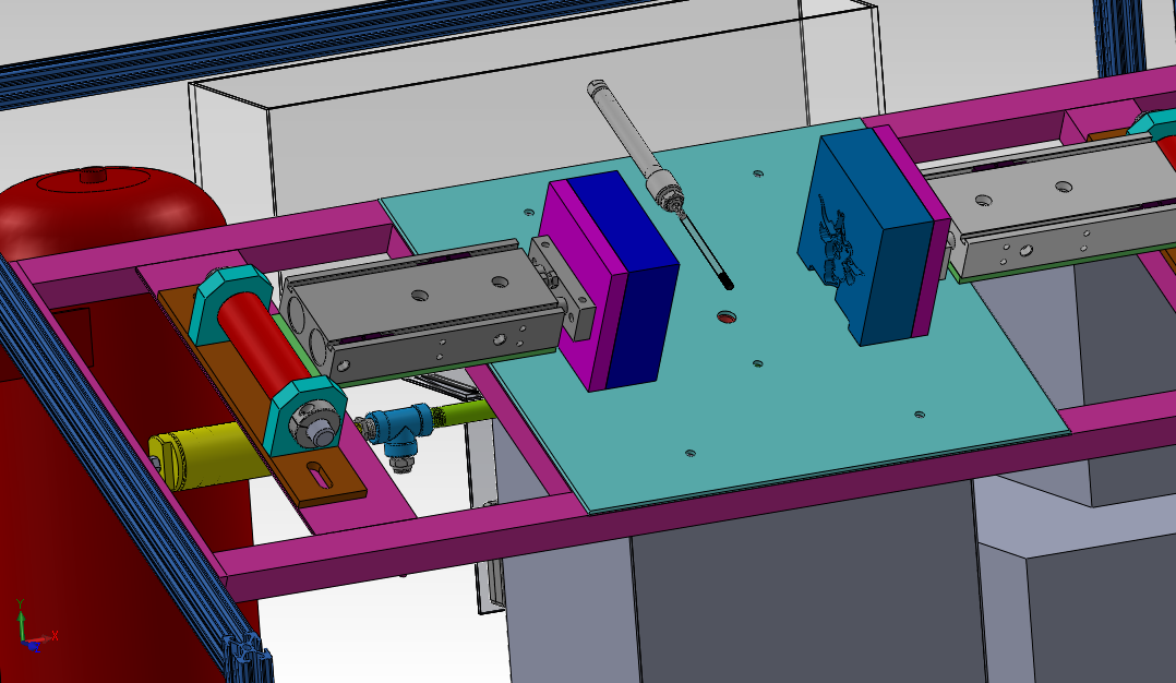
IMG_0284

Up next to install:

  • Plastic injection cylinder and mount
  • Mold cylinders and mounts
  • Compressor
  • Chiller


Protect Yourself! Building a Machine Cover

After nearly getting a serious burn from flying 240 degree plastic, I decided the molder’s cover needed to be moved up higher on the priority list:

IMG_0703

I think it’s actually closer to the middle of the priority list…

The original Mold-a-Rama used a bubble top  to protect the users (fitting for the 1950s theme of the machine). Here’s good guide on making one yourself:

http://www.recumbents.com/wisil/bubbles/hpvbubbles.htm

Since my machine is decidedly more industrial, I went with an aluminum frame made of 1″ x “1 x 1/8” aluminum angle with polycarbonate panels. Polycarbonate (aka lexan) is a better choice for a machine enclosure than say acrylic due to its higher impact strength. Acrylic will shatter upon impact. My molder’s cover completes the square profile of the machine (in green below). It hinges at the back and will latch (somehow?) in the front.

overview_2_15_13

After cutting the stock to size, I printed out a 1:1 outline of the sides.

IMG_0270

I welded one side, and then use that part as a jig for the other side.

IMG_0269

The two halves were welded tether with supports spanning the middle. I used an angle grinder and roloc disks to dress the welds. Since I wanted smooth joints, I needed to put a heavy bevel on the ends with the joints before welding. This allows you to have a smooth joint while still having weld remaning to hold the parts together.

After finish welding the frame, I cut to size the plexi panels on the table saw and peeled back a little of the protective film.

IMG_0693

Pop rivets are used to hold the panels to the frame. I used a washer on the back of the plexi panel to keep the rivet from pulling through.

IMG_0698

IMG_0697

For this project I got to borrow a pneumatic riveter. These are SO much better than a manual riveter. Since you don’t need to apply nearly as much pressure, it’s much easier to get the rivets to sit flat. Also less hand fatigue, double win.

IMG_0695

That’s it for the cover.

IMG_0699

Build Blitz Weekend 1

With the deadline for complete rapidly approaching, progress has stepped up. I spent most of my Saturday machining, welding, and cutting.

The bottom of the main valve on top of the injection cylinder has pipe threads to accept a compression fitting. One note about pipe tap, you need to be really careful about your tap depth. If you tap too deep with a tapered pipe tap you can end up in a situation where your fitting bottoms out before the threads tighten up, leaving you with a leaky pipe connection. So pay attention to that thread call out and test with a fitting if you are unsure.

IMG_0261

Here are all the parts for the injector valve assembly. This regulates the flow of plastic and air into the mold cavity via the shuttle valve sliding back and forth.

IMG_0262

Starting hole layout for the melt tank. I kind of wish I had used steel for the tank instead of stainless steel. Stainless is a real pain to work with. It’s hard to cut, hard to drill, hard to bend, hard to weld. Just really unfriendly in general. The original mold-a-ramas used an aluminum tank, but I got a really good deal on the stainless tank I started with to make this part.

IMG_0263

Another area where I’m differing from the original mold-a-ramas is the piston design. The original injection cylinder sealed agains the rod of the hydraulic cylinder used to inject plastic for the melt tank to the mold. In my design I have the seal on the piston. I’m very nervous excited to see how well this works. There is another disk, not shown, that will retain the seal against this piston.

IMG_0264 IMG_0265 IMG_0266


A few more from this weekend:

IMG_0267

I really need to hire a hand model.

IMG_0268


There are a few more bits and pieces that need to be fabricated (frame for cover, water tank, brackets for a few items), but the bulk of it is done. Next up is programming, wiring, and test/debug.

Mold Machine, Meet Welder

Metal met welder this week in the shop. I finished machining a few brackets and started tack welding some assemblies together.

Welding aluminum is tricky, the coefficient of thermal expansion is almost twice that of steel, which means it moves from the heat of the weld, much more so than steel. Here’s some tips when welding together plates of aluminum:

1. Aluminum moves during welding. A lot. Start slowly and clamp together anything that may warp or shift during welding.

m8 034

2. Check for square and check your dimensions, early and often. Since the material moves so much during welding, what started out nice and square will end up looking like a pretzel. So weld slowly and move around, alternately tacking on opposites sides (the heat from the weld has a tendency to pull the plates together on the welded side and apart on the opposite side. Recheck for square/level after very few tacks.

m8 035

3. I always find faces in the stuff I work on:

m8 036

I was able to tack together the complete injection cylinder, minus a small plate on top which I later added to give me a spot to bolt the valve block to.

m8 039

I also tacked together the swinging mold cylinder brackets:

m8 033 (1)

Having the mold cylinders swing up allows me to service the parts inside the melt tank without disturbing the alignment of the molds.

m8 038

m8 037

And the sub-frame that a majority of the machine gets attached to.

photo (13)

That’s it for now. Next up is cutting the 1×1 angle for the top cover and finishing some parts on the mill and lathe.

Mold-A-Rama Build Begins

I have spent the last 5 months designing, buying parts, redesigning, and buying more parts. I am finally at the point of cutting metal and bolting stuff together (the fun part). I have to say, it feels pretty good. Below you can see the 80/20 frame (mostly 1010 series with a lower frame made from 1020 series extrusion) , it is still missing a few crossbars near the top, as I hadn’t yet tapped the ends of the extrusion to accept a corner fitting.

I was initially concerned about how rigid the 1010 uprights would be given that the they are only attached to the bottom 1020 frame with two plates each. I found that it holds up surprisingly well to small amounts of force (hand applied), and this is even without the aluminum weldment that fills the space between the two angled bars. You can also just barely make out the waterjet cut 120 degree brackets on the front angle.

photo (12)

No longer just shapes on a computer screen.

I’m also very close to some initial tests with the pneumatics. I have new sensors for air cylinders that interface better with a micro controller, and have started breadboarding the transistors to drive the solenoids valves.

DIY Mold-A-Rama Update 3

A lot of progress has been made in the last few months on my version of the 1960’s classic Mold-a-Rama machine.

The design has been further refined

  • The frame where the mold cylinders attach has been changed from 80/20 to 1″ square aluminum tubing.
    • This change was made because I was having a hard time mounting and aligning the various components to the slots in the aluminum extrusion.
    • The mold halves will press against each other with several hundred pounds of force; the friction fit nature of t-slot construction would likely have failed under this load. The new frame is a one piece welded structure.
    • The new frame, while not re-configurable, will be much stronger and allow for easier alignment of the plastic tank and mold halves.

overview_2_15_13

  • The plastic pump has been completely redesigned
    • I’ve switched from a right angle gear motor to an air cylinder driven piston pump (think giant aluminum syringe)
    • This change eliminated a complex machined part ($$$) and replaced it with a much simpler welded tube and plate design ($)

melt pot complete_2_15_13

  • The actual mold cylinders have been selected
    • So much of the design decisions and components selections have been driven by what I can get on the surplus market  Case in point: the mold cylinders. I’ve seen that the actual mold-a-ramas have an enormous amount of play in their mold cylinders and mounts. I thought using a twin piston cylinder would help with the side loading on the pistons (due to the weight of the molds want to slide down on the angled frame. I found a good price for two twin piston SMC cylinder on eBay (with sensors and flow control fittings!)
    • I designed a robust mounting system using aluminum tube, bronze bearings, and 5/8″ steel shafting.

mold cylinders_2_13_15


Parts have been bought

I’ve also been spending quality time on eBay, at surplus stores, and throwing money at various other online retailers. Here’s where some of the money has gone:

photo 2

Left to right: Air compressor, air tank, compressor switch

The air compressor is a Thomas & betts unit I got at C&H surplus (super cool store, check it out if you’re in SoCal). It has twin cylinders and puts out more CFM at a lower decibel than most compact air compressors.

photo 3

Left to right: water pump, auger for plastic hopper, cartridge heaters

photo 1

The top two cylinders move the mold halves together, the bottom one moves the piston in the plastic injector, and the solenoid manifold on the right controls it all.

photo 4

50lbs of hard to find plastic

The ability to buy the plastic pellets was a make or break moment for this project. There were not a whole lot of suitable replacements for this particular plastic (more specifically, polyethylene wax). Fortunately the west coast distributor for this happened to be close and had several bags it was willing to sell to me (normally this product only sold in 1000kg pallets, which is about 950kg more than I need). Getting a hold of this was a major load off my mind.

BA6JS4JCcAAwIJm

It’s like the warehouse in Indiana Jones, but instead of ancient relics there’s plastic resin.

I’ve begun cutting metal for the frame and plastic melt pot, hopefully welding will start this week!

Cardboard Mockup: The Original Rapid Prototyping

I often find it hard to get a sense of scale when designing things using CAD software. Staring at a model on a 24″ screen can sometimes make small objects look massive, and large objects tiny. Placing  references (such as a person) next to your model helps some, and there are many free human models for pretty much all CAD platforms. However nothing beats a physical prototype. If your part is small enough 3D printers are perfect. For larger parts you have to get creative. The final frame will be made of 80/20 aluminum framing, but I did not want to commit to cutting it up just yet, as I was still playing with the frame dimensions. I needed a cheap material that was easily formable, yet sturdy enough to hold its own weight, next to my door was the answer: double wall cardboard.

Just as architects use cardboard to construct scaled down buildings, I built a 1:1 model of my mold-a-rama replica. Using only packing tape and cardboard, I was able to quickly (and cheaply) build a model that’s accurate to about 0.25″.

I started by measuring the outside dimensions of my model in solidworks, and transferring those to cardboard. Here’s some tips I learned from doing it:

  • The boxes I had on hand were medium to small-sized, with fold lines all over. If you can’t cut around the lines, take another piece of cardboard and tape it over the fold line to reinforce it.
  • Reinforce the corners by making a long  L-bracket and tape it to the inside.
  • Cardboard tabs can be used to prop up unsupported spans of cardboard.
  • Get some good blades for your utility knife, I like Irwin bimetal blades. They make cutting through thick double wall cardboard a breeze.

And here’s the end result:

Cardboard mockup

Those 3rd grade arts and craft skills are finally paying off.

As I suspected it was bigger in full-scale than what I thought it would have been.

Another benefit is that the interior volume is very close to the usable space inside the actual machine. I was able to place most of the bulkier components inside, allowing me to play with layout:

Interior layout

From left to right: air compressor, injection cylinder, plastic melt tank, water pump (blue thing peeking out), water chiller.

Moving components around inside the cardboard model was so much faster than doing it in CAD. It also gave me a better idea of how much space I need between components.

The layout above is mostly complete. I have since gotten an air tank that sits in the back left corner. The stainless box you see is the starting point for the plastic melt tank (I’ll go into more detail in the next post where I’ll show off some of the components  that have already been bought)

This method really only works if what you are building is mostly flat panels that meet at right angles. If you’ve got a contoured model and you are set on using cardboard, make an STL file of your part with layers that match your cardboard thickness and print out patterns. This can be done using the free software AutoCad 123D (http://www.123dapp.com/make)