
I often find it hard to get a sense of scale when designing things using CAD software. Staring at a model on a 24″ screen can sometimes make small objects look massive, and large objects tiny. Placing references (such as a person) next to your model helps some, and there are many free human models for pretty much all CAD platforms. However nothing beats a physical prototype. If your part is small enough 3D printers are perfect. For larger parts you have to get creative. The final frame will be made of 80/20 aluminum framing, but I did not want to commit to cutting it up just yet, as I was still playing with the frame dimensions. I needed a cheap material that was easily formable, yet sturdy enough to hold its own weight, next to my door was the answer: double wall cardboard.
Just as architects use cardboard to construct scaled down buildings, I built a 1:1 model of my mold-a-rama replica. Using only packing tape and cardboard, I was able to quickly (and cheaply) build a model that’s accurate to about 0.25″.
I started by measuring the outside dimensions of my model in solidworks, and transferring those to cardboard. Here’s some tips I learned from doing it:
- The boxes I had on hand were medium to small-sized, with fold lines all over. If you can’t cut around the lines, take another piece of cardboard and tape it over the fold line to reinforce it.
- Reinforce the corners by making a long L-bracket and tape it to the inside.
- Cardboard tabs can be used to prop up unsupported spans of cardboard.
- Get some good blades for your utility knife, I like Irwin bimetal blades
. They make cutting through thick double wall cardboard a breeze.
And here’s the end result:

Those 3rd grade arts and craft skills are finally paying off.
As I suspected it was bigger in full-scale than what I thought it would have been.
Another benefit is that the interior volume is very close to the usable space inside the actual machine. I was able to place most of the bulkier components inside, allowing me to play with layout:
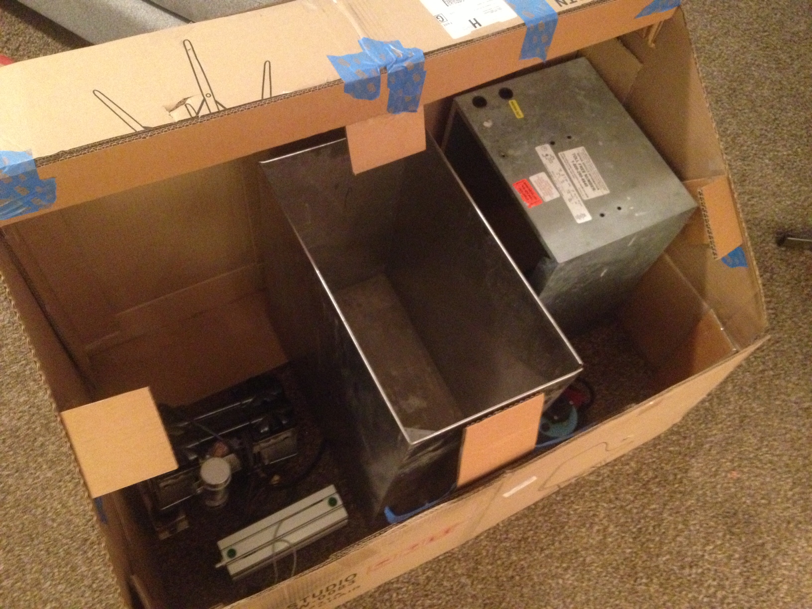
From left to right: air compressor, injection cylinder, plastic melt tank, water pump (blue thing peeking out), water chiller.
Moving components around inside the cardboard model was so much faster than doing it in CAD. It also gave me a better idea of how much space I need between components.
The layout above is mostly complete. I have since gotten an air tank that sits in the back left corner. The stainless box you see is the starting point for the plastic melt tank (I’ll go into more detail in the next post where I’ll show off some of the components that have already been bought)
This method really only works if what you are building is mostly flat panels that meet at right angles. If you’ve got a contoured model and you are set on using cardboard, make an STL file of your part with layers that match your cardboard thickness and print out patterns. This can be done using the free software AutoCad 123D (http://www.123dapp.com/make)

Good way of telling, and good paragraph to get facts about my presentation subject
matter, which i am going to convey in college.