Sherline 2000 Solid Column Conversion

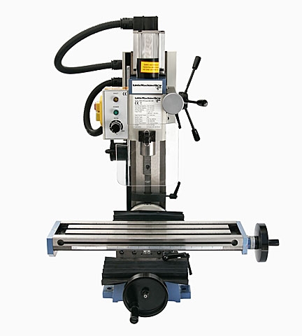
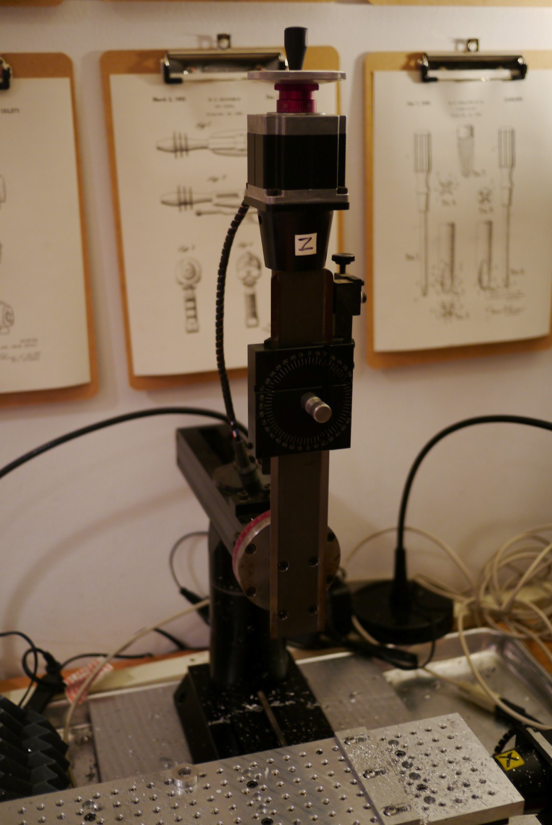
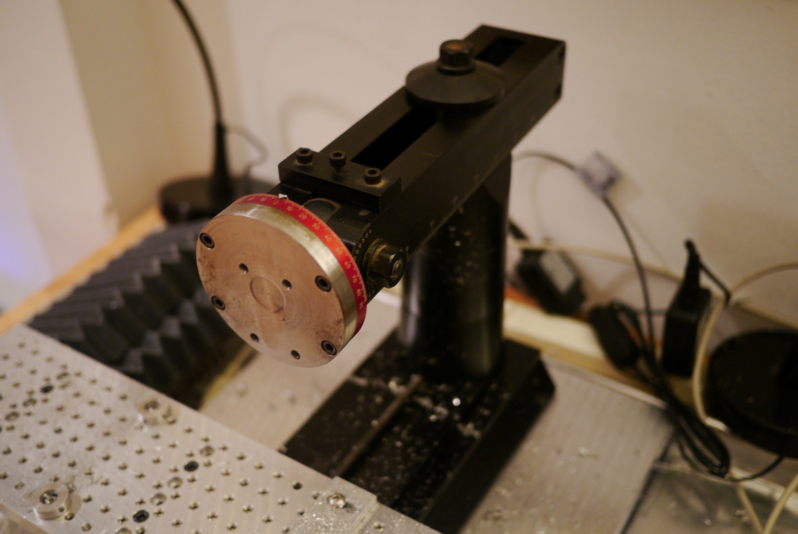
A while back I finished the CNC conversion of the Sherline 2000 mill I bought off craigslist. Now that I’ve had a chance to use it I can say it fails in a few respects. First is that it is a pain to tram, there are so many axis with movement that it takes forever with a DTI (dial test indicator.) I got a nano tram off eBay, but did not have any luck getting that to work. Checking with a DTI after aligning it showed it was consistently off in both axis by about 0.005-0.008″ or more. The instructions say to use a feeler gauge to fine tune the alignment, but that kind of defeats the point of its supposed dead simple alignment procedure.

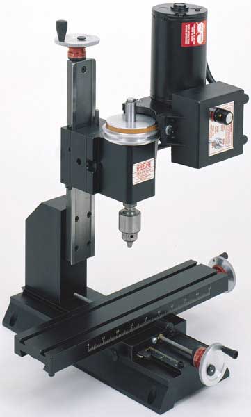
The second issue is that the head stock gets knocked out of alignment by taking some pretty light cuts in aluminum (~0.010″ depth of cut). No matter how much I cleaned the mating surfaces and tightened the bolts, the column still shifted.

The adjustable headstock may be useful for certain weird setups, but unless you are cutting exclusively plastics or wood I cannot recommend it.

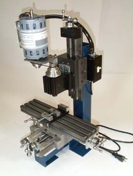
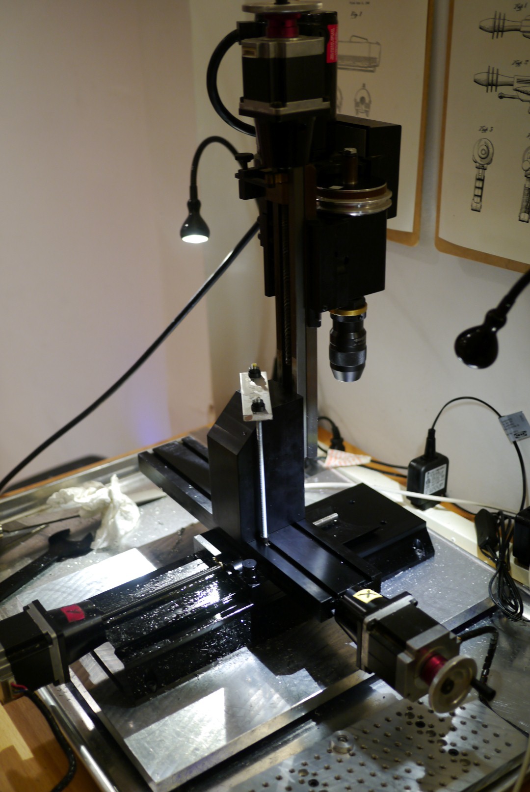
After ruining one last part on the 2000 mill, I decided to convert it to the solid column of the 5400. Since I reused the existing 14″ base, I ended up with a mill that has 2″ more Y travel than the 5400.

If you want to do this conversion you’ll need to order PN 50050 from Sherline, I paid $48.00 + shipping for it.

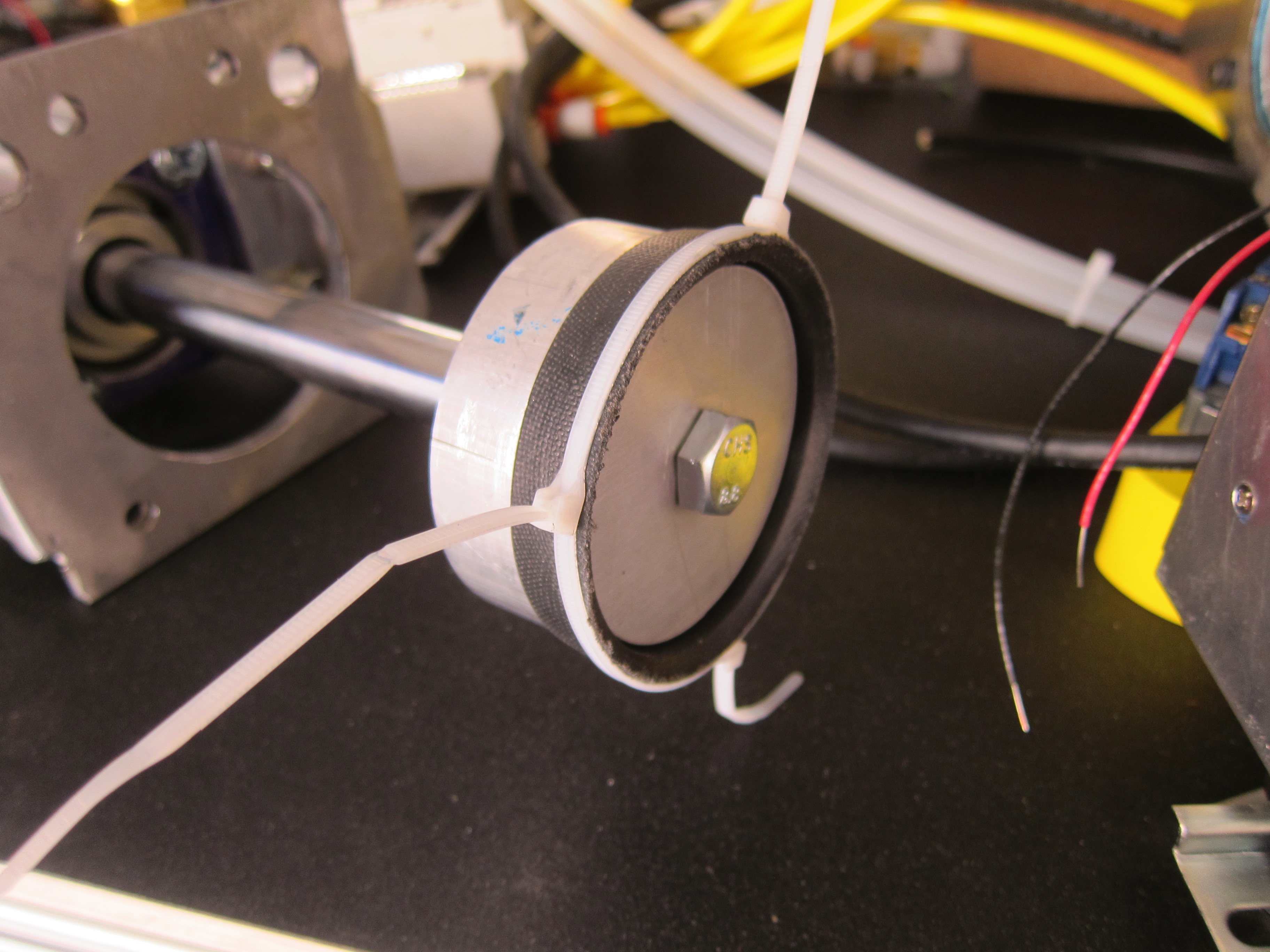
The conversion starts by removing the head stock.

P1020490 (Large)

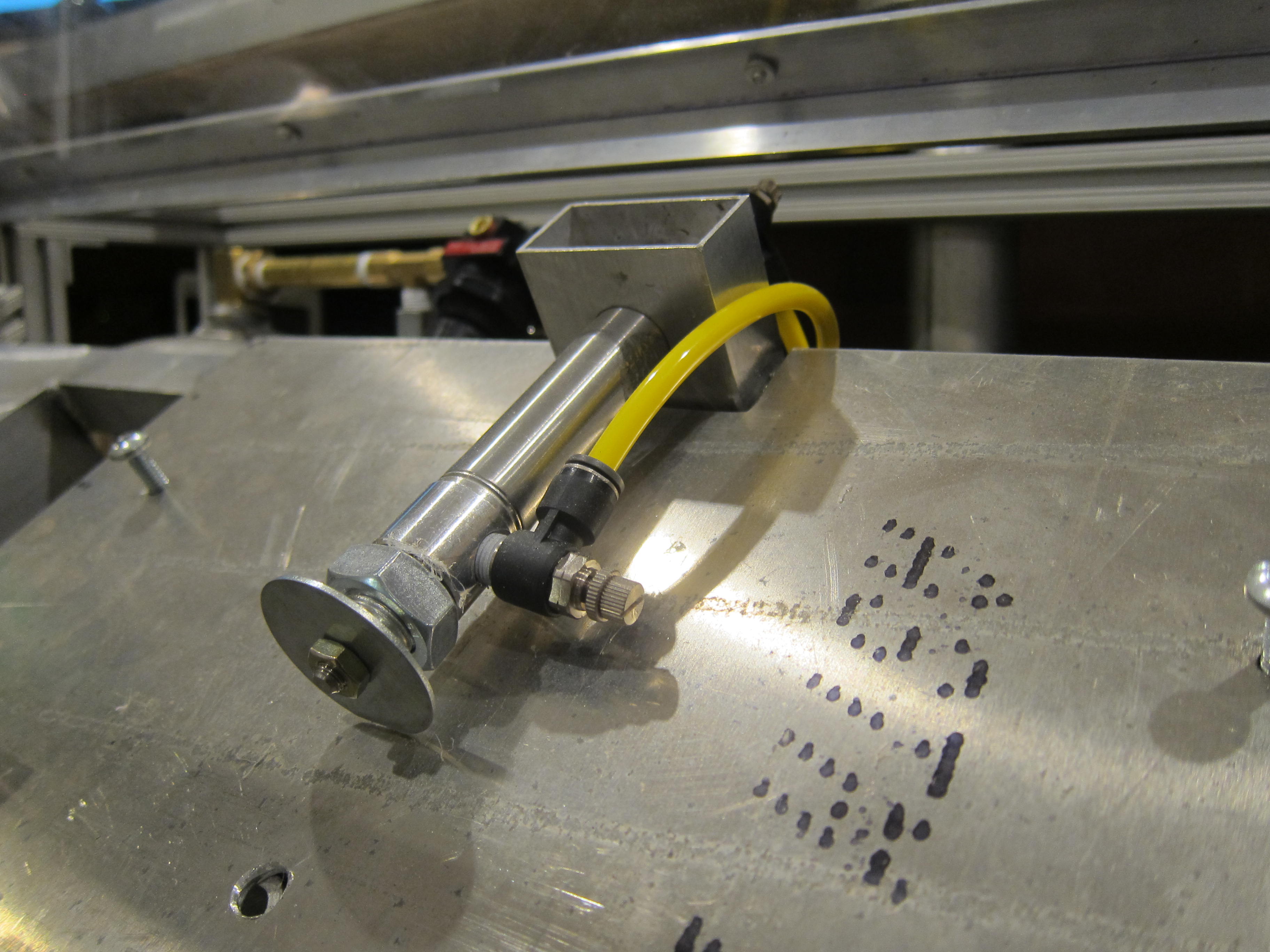
Unbolting the z axis dovetail

P1020491 (Large)


And removing the column assembly

P1020493 (Large)

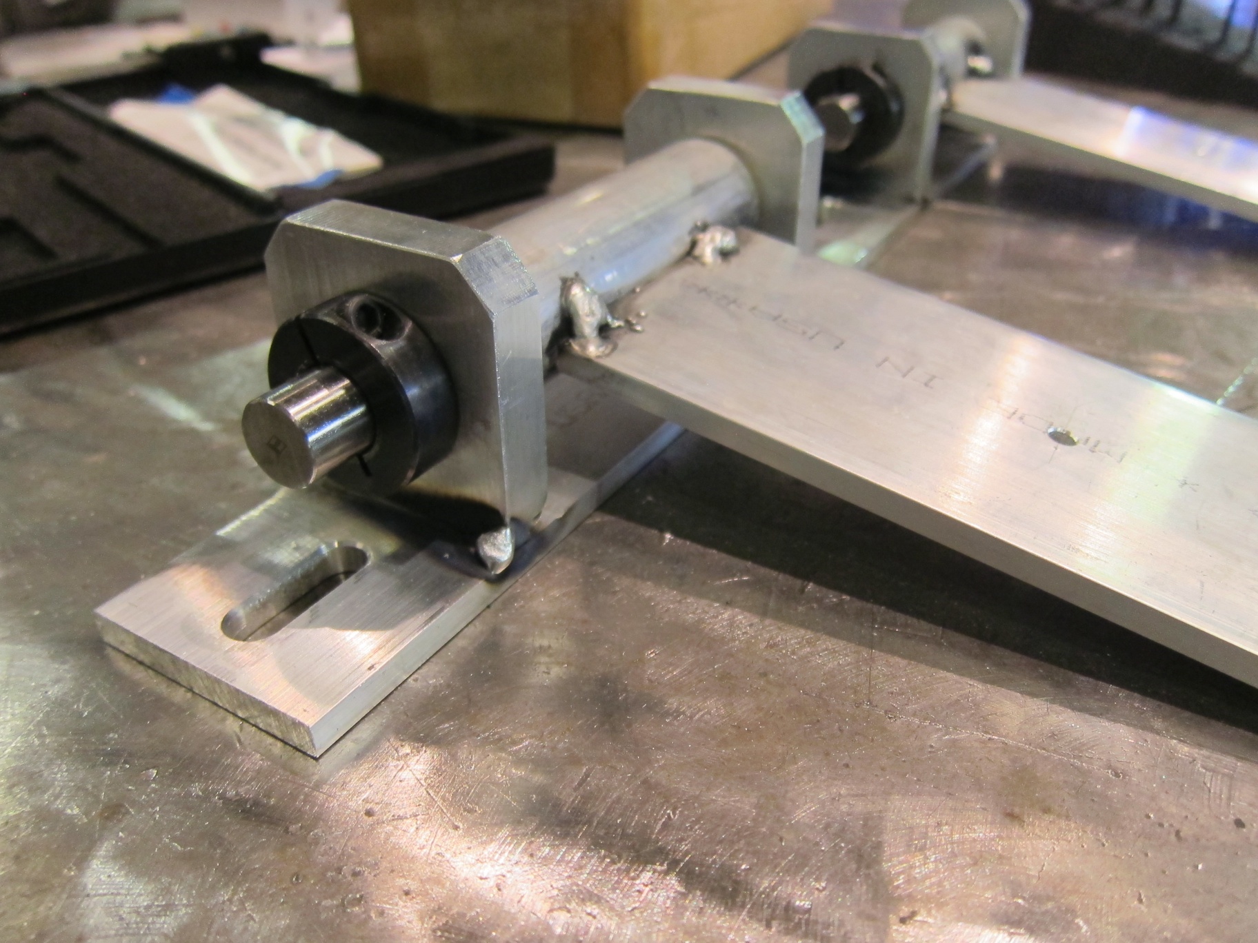
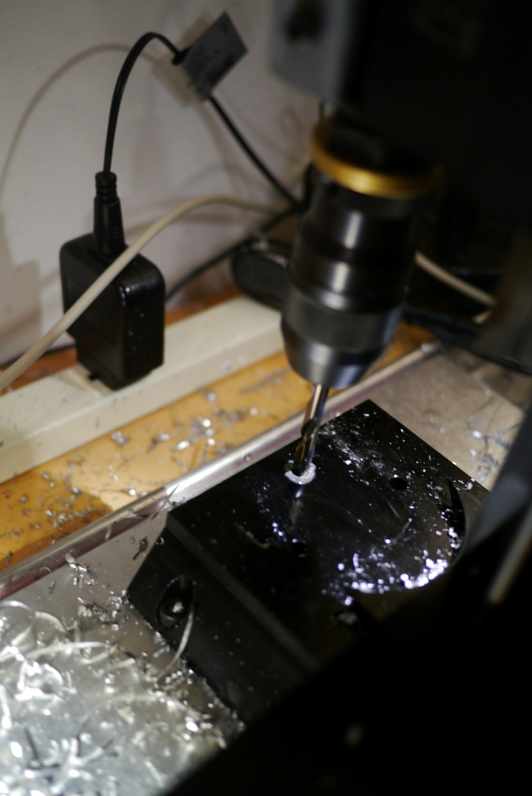
For some reason the bolt pattern on the base of the 2000 mill is different than that of the 5400 mills, so you need to drill two new holes to mount the column. This guy has a clever way of turning the mill on itself to drill said holes. I followed his method, using pieces of 10-32 all thread and a piece of .25″ x 1.00″ aluminum flat bar.

P1020505 (Large)

P1020504 (Large)

Here’s a drawing of the new hole pattern I made. Note that the column bolts are not centered between the dovetail in the base (which is why the circular 2000 column cut out is not even). Basically drill two holes .5″ from the rear edge, spaced 2″ apart and centered between the edges of the base, with a letter F (.257″) drill.

image001


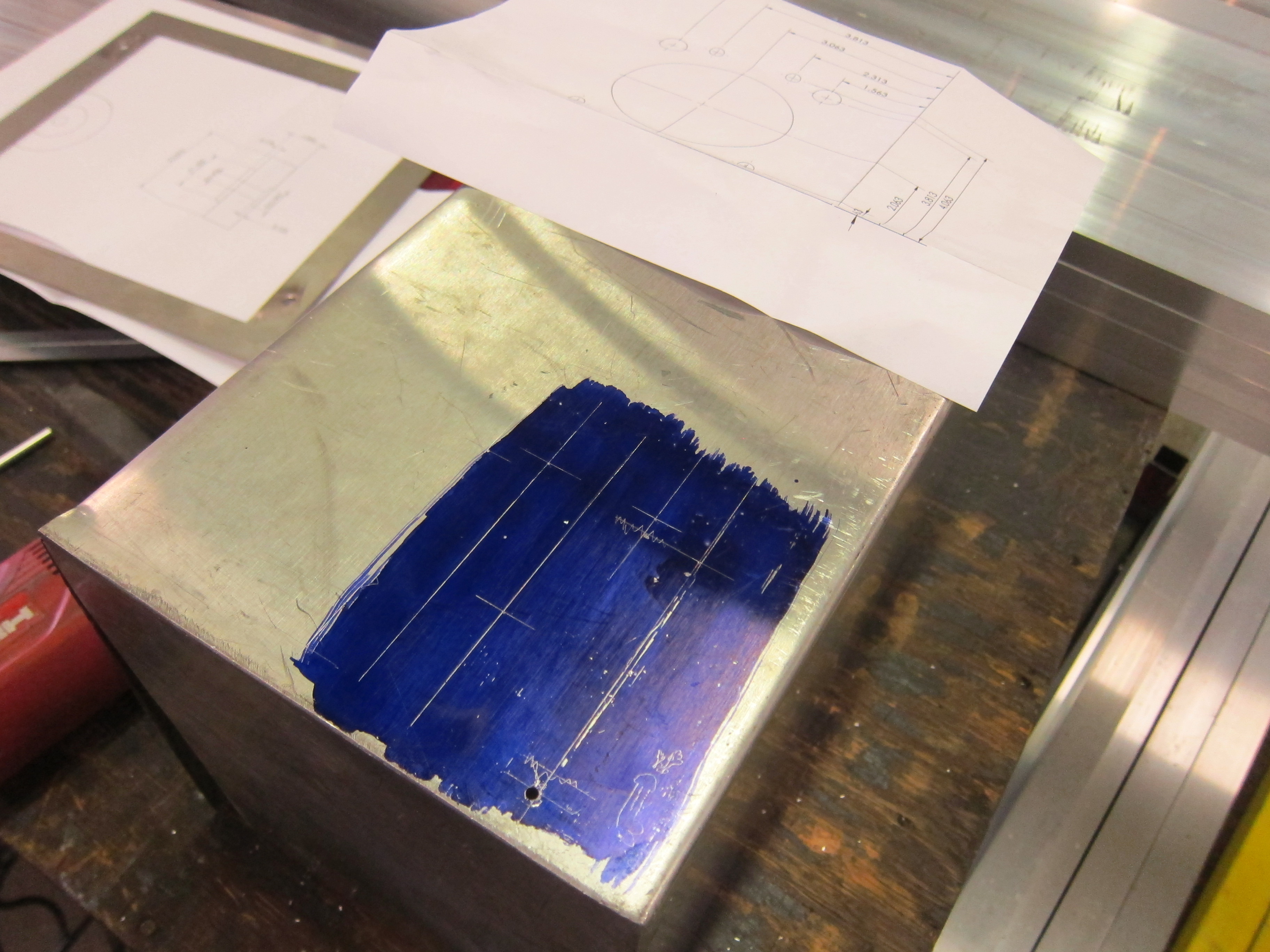
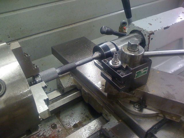
I scribed lines into the base and aligned the drill using the pointed end of my center finder.

P1020510 (Large)

And drilled with a center drill followed by a letter F drill bit.

P1020511 (Large)

P1020519 (Large)

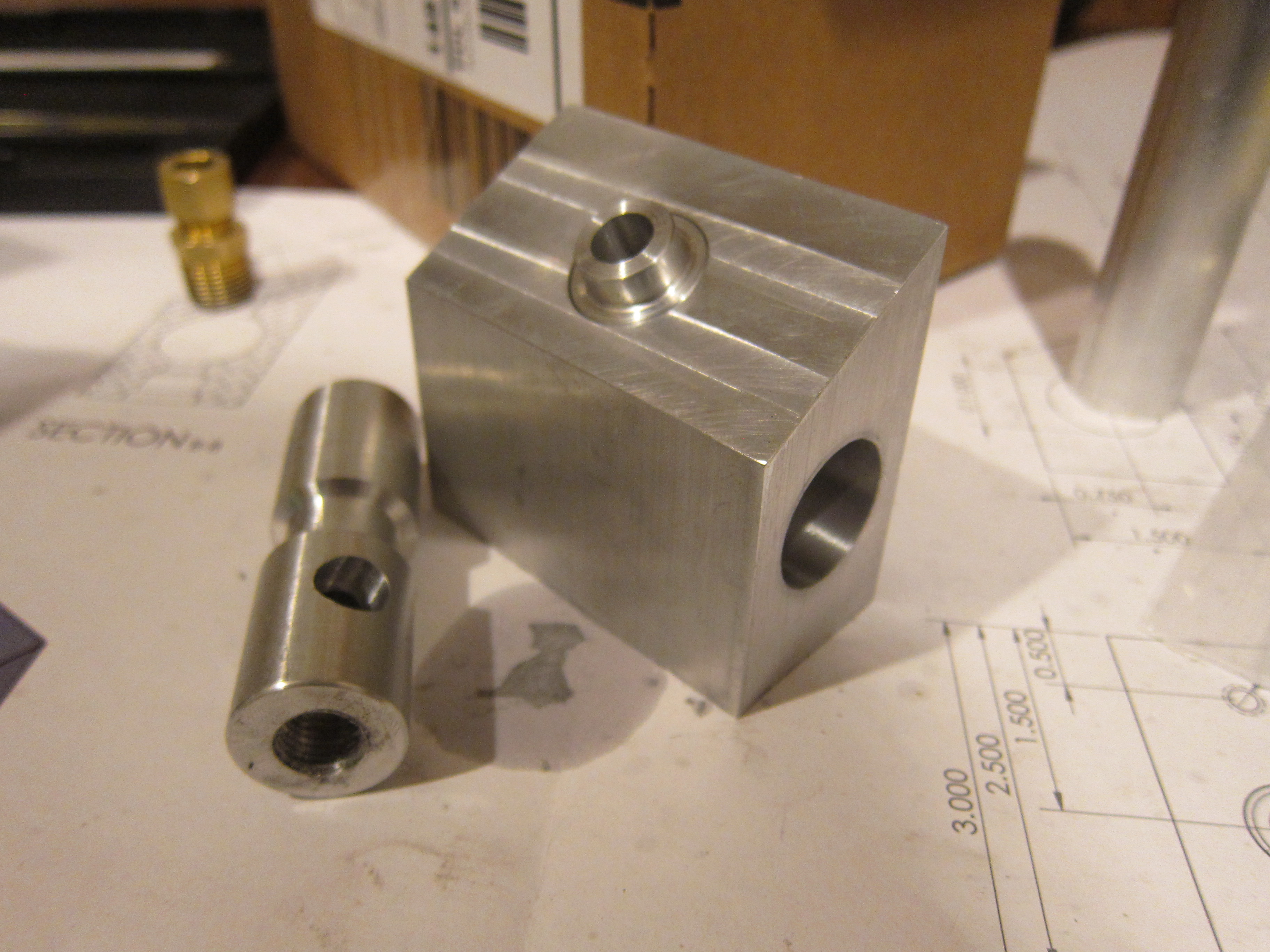
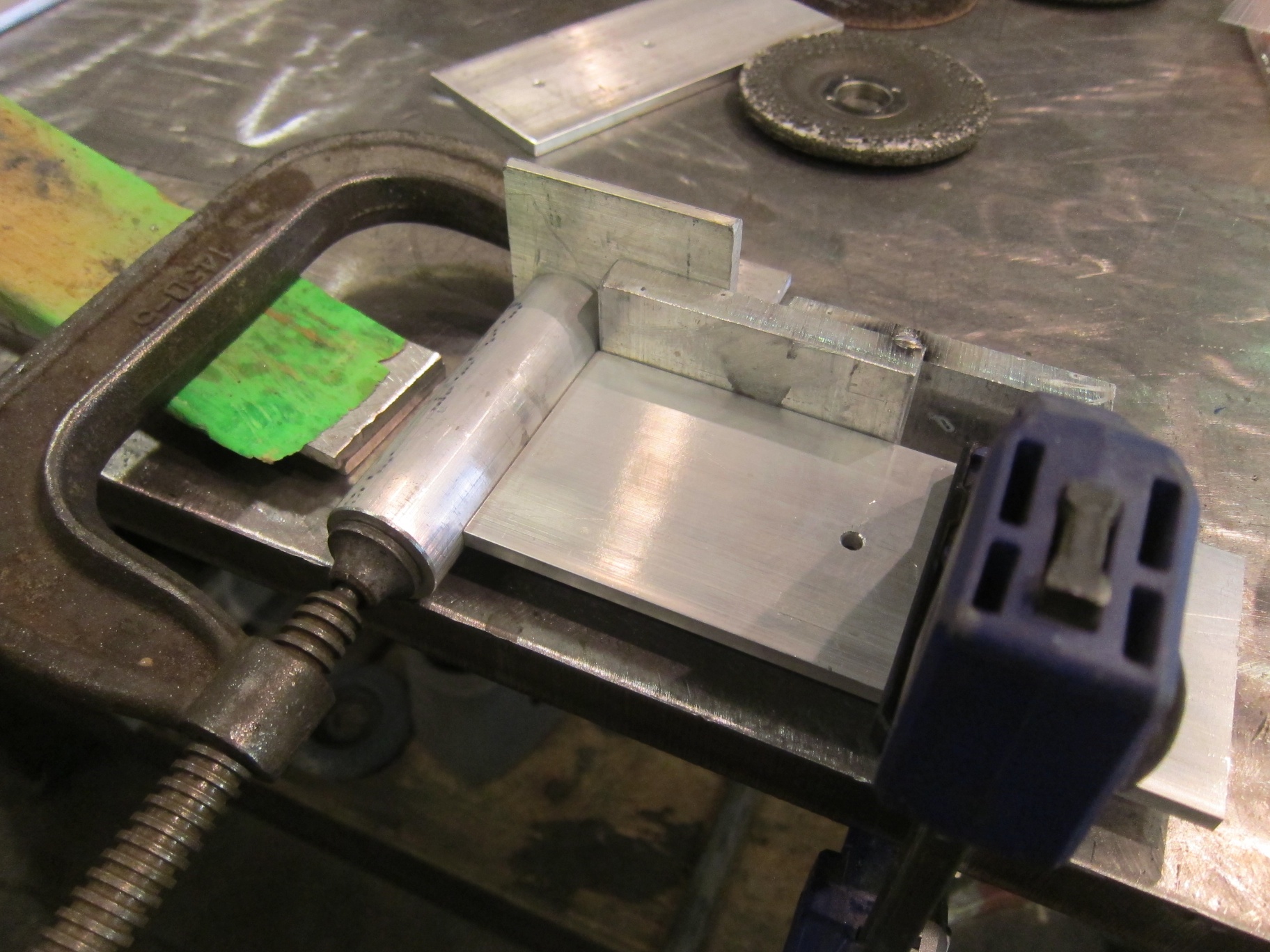
The solid column still will not bolt to your 2000 base at this point as there is interference between the column base and those little pointed ends of the dovetail. Rather than machine those off I made a spacer from a piece of 5/8″ cast tool plate I had leftover from the mounting plate I made for the mill.

P1020778 (Large)

Depending on how your mill base is mounted you’ll either need to counter bore the underside of the column mount holes in the base to accept a cap screw, or use a low head 1/4-20 bolt. I chose to do the latter.

One more thing, make sure you remove the z-axis drop down bracket from the z-axis nut. You don’t need this anymore and it will prevent the head stock from raising all the way up, limiting your z-axis travel. The 2000 mill needed it so that the headstock could lower all the way to the table.

Once the bracket is removed, you’ll need to use a shorter screw to attach the z-axis backlash bracket. Or use a spacer like I did.

P1020770 (Large)


The left over parts.

P1020766 (Large)

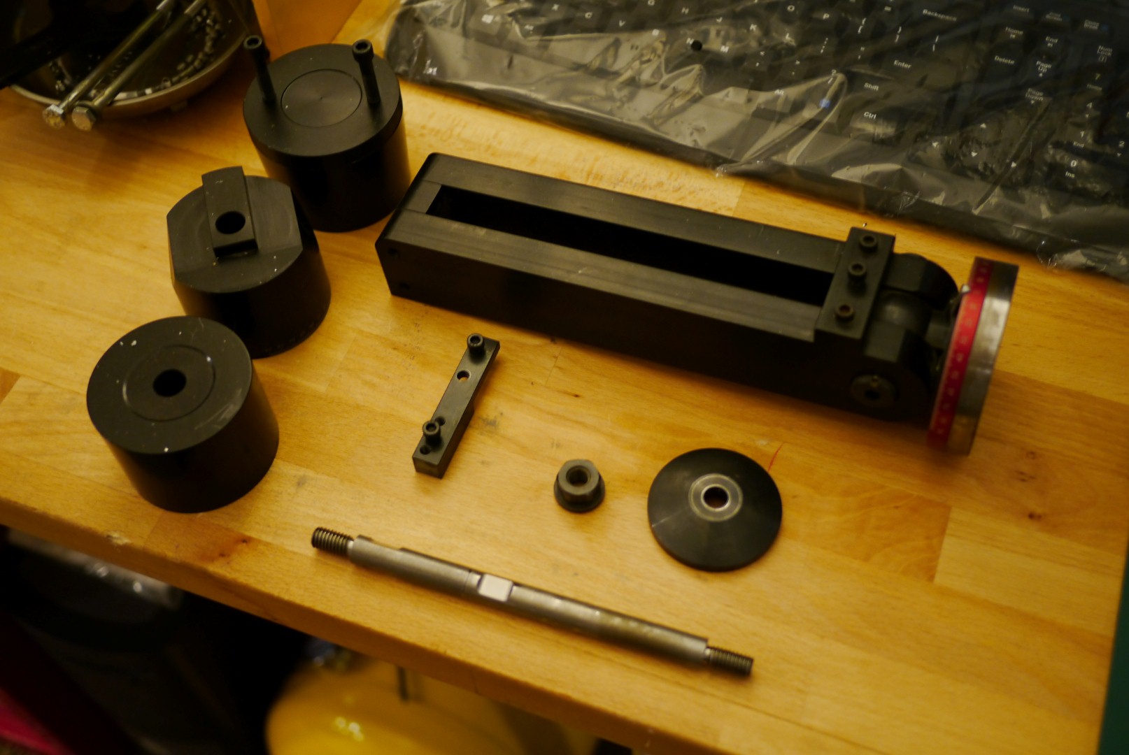
I’ll probably keep these around in case I sell the mill, or if for some reason I come across a setup that requires them.

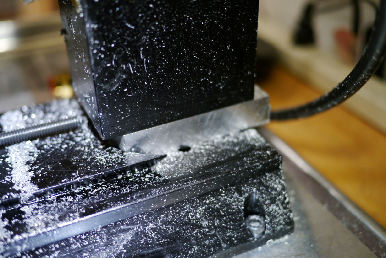
After the upgrade the difference is night and day while cutting aluminum. Much reduced chatter, more aggressive cuts possible, and the column stays in alignment. It’s like getting a whole new mill for $50.


Advertisement

The Apartment Workshop Series: Mini Mill

I’ve been thinking about getting my own mill for several years. I just like the idea of being able to shape metal. For the type of odd ball projects I like, I end up making a lot of my own parts, or customizing off the self ones. Having a mill allows me to do that easier and with much greater precision. I briefly looked at 3D printers, but parts produced on them have such low mechanical strength they really aren’t suited to my projects. Plus I like the idea supporting subtractive manufacturing (milling), as all anyone ever talks about is additive manufacturing (3d printing) these days.

Picking a mill can be a daunting task. There are so many factors to consider: price, working envelope, CNC or manual, construction, spindle type, etc. Being that I planned on operating this inside my living room, my options quickly narrowed. After much research I found several machines that fit the bill:

Little Machine Shop 3900 Solid Column mini mill

480.3900

Taig Micro Mill

nmmill19a

Sherline 2000/5400

5400pic

The taig and sherline are a closer match, as the LMS mill is more of a mini mill, while the others are more micro mills. The LMS mill was my favorite due to the much heavier construction, more powerful motor, and standard r8 spindle. However it is just slightly too large, on it’s own it is not that big, but when you factor in that it will need an enclosure (which is kind of a must have if you plane on running a mill inside your house) it just get’s too big.

Between the taig and sherline, I prefer the taig. It’s heavier steel construction make it much stiffer than the all aluminum sherline. Neither one will handle steel all that well, both can easily do plastic, but for aluminum the extra rigidity of the taig helps reduce chatter.

I was all set to buy a taig, but I came across a deal I could not pass up on craigslist. I got a sherline 2000 CNC ready mill, with steppers for less than 1/3rd the retail price. Whoever was using it last was cutting wood, as there are wood particles all over. It will need to be disassembled cleaned and lubed before use.

photo-2

It fits very nicely on my workbench, and even when an enclosure is added it should not hog too much of the work surface. It did not have a control box, so I’ll need to start looking at stepper drivers, power supplies, and machine control software. Looking forward to this!

Sealing it

With the melt tank installed and the pump body assembled, I can now start fitting the injection cylinder to the tank. The large (50mm!) air cylinder moves a piston in the pump body to draw in molten plastic, and then force it into the mold cavity. The piston seals to the pump body with a cup seal. The original mold-a-rama actually has no seal on the piston itself, it seals around the shaft of the injection cylinder, the seal can be seen here:

DSCF5337

This is the injection ram of the mold-a-rama. The seal is in the center of the picture on the aluminum plate, the fiberglass insulation is covering the tank.

Installing the seal was a real bear. The cup seal is sized for a 3″ cylinder, it flares out to ~3.25″ OD to press against the cylinder walls. I needed to compress is to fit it into the cylinder. Softening the seal really had no impact on it’s flexibility, what I really needed was a piston ring compressor. Lacking that I used several daisy chained cable ties. That still didn’t work well so I used some plastic tools to push the seal in.

IMG_0290

I wasn’t sure what to use to insulate the melt tank until a fateful trip to Lowes. In the pipe insulation section I found this self-adhesive aluminum foil backed foam tape. The adhesive holds up to the tank temperatures, and the heat radiating off the tank is noticeable reduced (as measured using the calibrated portion of the back of my hand).

IMG_0292

I looked long and hard for a plastic water tank that was compact, but had a large enough opening to fit the water pump through. The water pump is supposed to be submerged in the water tank, this  will extend the pump life by keeping it cooler. I gave up on finding a plastic tank and made a metal one myself. The body is made from 6″x6″x.120″ wall aluminum tubing with a water jet aluminum flange and lid. A cable gland seals around the power cable. The gold cylinders sticking out from the flange are rivnuts, those along with thumb screws will allow tool-less removal of the water tank  lid for refills. I plan to add a sight glass later on so I can check the water level with out removing the lid.

IMG_0712

The mount for the mold delivery cylinder (the one that pushes the finished plastic part into the retrieval bin) is made from a small piece of 1″x3″ aluminum tubing welded to the top frame and a shaft collar.

IMG_0713

The lower half of the aluminum shaft collar is welded to the back of the rectangular tubing, the upper half is free  and is what clamps onto the cylinder.

IMG_0714

The molder is pretty awkward to move around as it doesn’t sit on a wheeled base. I added handles to each side to make moving it a little easier. The first set of handles I got from McMaster were plastic, thinking the machine couldn’t weight more than 100-150lbs, it turns out I forgot to take into account two very heavy items: the water chiller and the compressor. After putting those in, the machine weights closer to 200lbs. The plastic handles were quickly swapped out for some beefy aluminum ones. I’ll still probably move the machine with the compressor and chiller removed, but now I have a lot move confidence in the handles while moving the machine.

IMG_0717

And finally, before I go, a sneak peak of the new molds!

IMG_0725

Build Blitz Weekend 1

With the deadline for complete rapidly approaching, progress has stepped up. I spent most of my Saturday machining, welding, and cutting.

The bottom of the main valve on top of the injection cylinder has pipe threads to accept a compression fitting. One note about pipe tap, you need to be really careful about your tap depth. If you tap too deep with a tapered pipe tap you can end up in a situation where your fitting bottoms out before the threads tighten up, leaving you with a leaky pipe connection. So pay attention to that thread call out and test with a fitting if you are unsure.

IMG_0261

Here are all the parts for the injector valve assembly. This regulates the flow of plastic and air into the mold cavity via the shuttle valve sliding back and forth.

IMG_0262

Starting hole layout for the melt tank. I kind of wish I had used steel for the tank instead of stainless steel. Stainless is a real pain to work with. It’s hard to cut, hard to drill, hard to bend, hard to weld. Just really unfriendly in general. The original mold-a-ramas used an aluminum tank, but I got a really good deal on the stainless tank I started with to make this part.

IMG_0263

Another area where I’m differing from the original mold-a-ramas is the piston design. The original injection cylinder sealed agains the rod of the hydraulic cylinder used to inject plastic for the melt tank to the mold. In my design I have the seal on the piston. I’m very nervous excited to see how well this works. There is another disk, not shown, that will retain the seal against this piston.

IMG_0264 IMG_0265 IMG_0266


A few more from this weekend:

IMG_0267

I really need to hire a hand model.

IMG_0268


There are a few more bits and pieces that need to be fabricated (frame for cover, water tank, brackets for a few items), but the bulk of it is done. Next up is programming, wiring, and test/debug.

Mold Machine, Meet Welder

Metal met welder this week in the shop. I finished machining a few brackets and started tack welding some assemblies together.

Welding aluminum is tricky, the coefficient of thermal expansion is almost twice that of steel, which means it moves from the heat of the weld, much more so than steel. Here’s some tips when welding together plates of aluminum:

1. Aluminum moves during welding. A lot. Start slowly and clamp together anything that may warp or shift during welding.

m8 034

2. Check for square and check your dimensions, early and often. Since the material moves so much during welding, what started out nice and square will end up looking like a pretzel. So weld slowly and move around, alternately tacking on opposites sides (the heat from the weld has a tendency to pull the plates together on the welded side and apart on the opposite side. Recheck for square/level after very few tacks.

m8 035

3. I always find faces in the stuff I work on:

m8 036

I was able to tack together the complete injection cylinder, minus a small plate on top which I later added to give me a spot to bolt the valve block to.

m8 039

I also tacked together the swinging mold cylinder brackets:

m8 033 (1)

Having the mold cylinders swing up allows me to service the parts inside the melt tank without disturbing the alignment of the molds.

m8 038

m8 037

And the sub-frame that a majority of the machine gets attached to.

photo (13)

That’s it for now. Next up is cutting the 1×1 angle for the top cover and finishing some parts on the mill and lathe.

Lost Foam Casting

Most twelve-year-old’s idea of a crazy project is building a Lego car or a tree house. Mine was to build a backyard foundry. I’m not sure where I got the idea from, but I think it was seeing an advertisement for Dave Gingery’s series of books in the back of Popular Mechanics. Dave Gingery created a whole series of instructional booklets and plans for the home machinist. He had books on how to build just about any piece of equipment from lathes to band saws to foundries.

Fortunately I had a father who, when presented with the idea of his twelve-year-old heating aluminum to a liquid state, not only encouraged me, but helped me gather all the necessary equipment. He also kept an eye on me, ensuring I didn’t end up in the ER’s burn unit or on an episode of “World’s Most Bizarre Backyard Accidents.”

The Actual furnace was made from a large popcorn can lined with a sand/fire clay mix, and heated with charcoal. We used a blower motor from a discarded dishwasher to raise the furnace temperature high enough to melt aluminum. My dad came up with the clever idea of using a stainless steel camping mug as a crucible. The end result was pretty similar to what you see below.

Continue reading

Machine Shop Madness

Being able to operate basic machining equipment should be an essential skill for every mechanical engineer. It’s really sad how often I hear 3rd and 4th year ME students say they have virtually no practical engineering skills. Granted most ME’s will never be required to operate a lathe or mill as part of their job, knowing the capabilities of the tools that will be producing your products helps you when designing those very same products. College teaches you a lot of equations and methodology, but you don’t really learn anything useful until you start designing and building stuff with your hands. So when I had the chance to take the machine shop course offered by my school I jumped at the opportunity.

Fortunately for me I have access to equipment most home machinists can only dream about. This is a Bridgeport vertical mill with a DRO on the x and y-axis. The device hanging off the right end of the table is a power feed, which comes in handy when making long slow passes in the x direction.

IMG_0170

Continue reading

A Little Machining

Single point threading is pretty wild. You’ve got about 15 levers, dials and knobs to keep track of. If you mess up and cross thread your part you have to start over, there really is no fixing it. Fortunately for me everything went well and a 1/2-20 nut threaded onto the shaft smoothly. This is a practice part before I start machining my actual parts.