Building a CNC Mill Stepper Driver

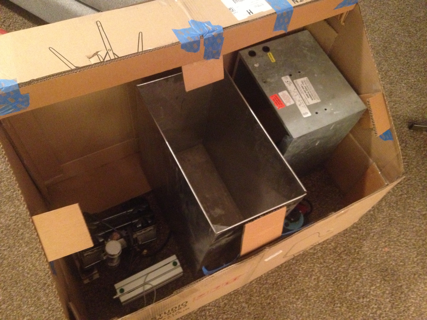
When I bought my Sherline mill, it came with stepper motors, but no driver box. The drive box takes the output from a PC parallel port (small electrical signals indicating which axis should move and in what direction).

Drive boxes contain several essential parts:

  1. Power supply
  2. Stepper motor drivers
  3. Break out board
  4. Connectors
  5. Fuses and wiring

I’m kind of particular about the control electronics of a piece of equipment. Control electronics should be layout in such a way that they are easily serviced. Nothing worst than trying to trace down a problem in a rats next of wiring. Below is as list of some practices I like to use when laying out an electronics enclosure.

  1. Components should be spaced to allow airflow around them
  2. Components should be removable without taking out an inordinate amount of other components
  3. Mount components to a removable panel, rather than directly to the enclosure
  4. Wiring should be neatly bundled, using removable wiring loom where possible
  5. Removable connectors are preferred over soldered connections
  6. Wire ferrules should be used when making connections to terminal blocks.
  7. Wiring going to a removable external panel should have extra length to allow the panel to be removed without straining connections (called a service loop)

Finding the right enclosure was probably the hardest part of this project, mostly because I had many criteria.

  1. Mostly made of metal
  2. Top should be removable without taking front or rear panel off
  3. Removable front and rear panels
  4. At least 10″x10″ and ideally ~4″ tall (based on some rough dimensions of the power supply and driver)
  5. Less than $50

I found several enclosures that fit a few of the requirements, such as:

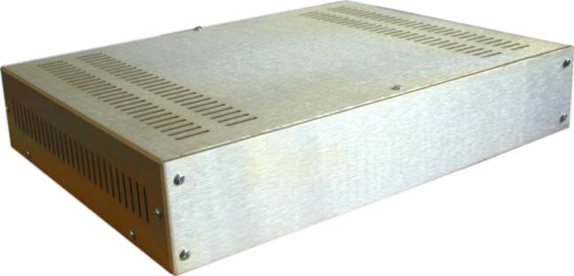
Par-metal table top series. Nice, but too much money.

20s01

Circuit Specialists EM Series Price is right, but a little too tall.

em-04-0The one I settled on was from eBay, but I also found it on amazon

$_57

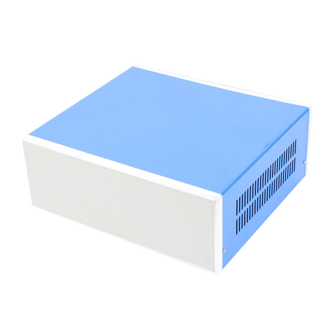
This enclosure fit all my criteria. My only gripe with it would be that the front and back panel are plastic and snap in place instead of using screws.

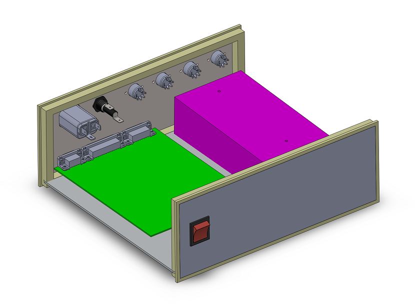
As I mentioned above, mounting components such as drivers and power supplies to a removable panel inside the enclosure makes assembly and service much easier. Parts can be installed and wired on the bench and the panel can be placed into the enclosure in one shot. This is a pretty common practice in industrial control panels. In fact, most enclosure suppliers (like Hoffman) sell panel kits that fit into their enclosures.

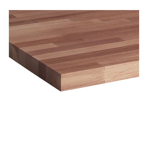
I took measurements of the inside of my enclosure and cut a panel out of 0.090″ aluminum sheet. 1/4″ nylon spacers and 8-32 hardware secure the panel to the enclosure. To find the position of mounting holes, I printed out a 1:1 scale outline of the power supply and laid it down next to the driver adjusting their relative locations until I was happy with the clearance.

IMG_4384

IMG_4386

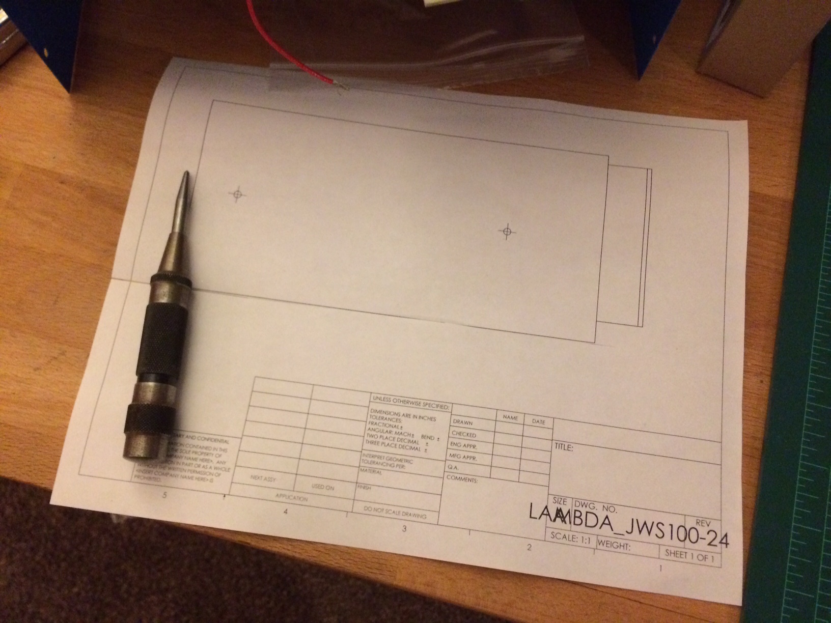
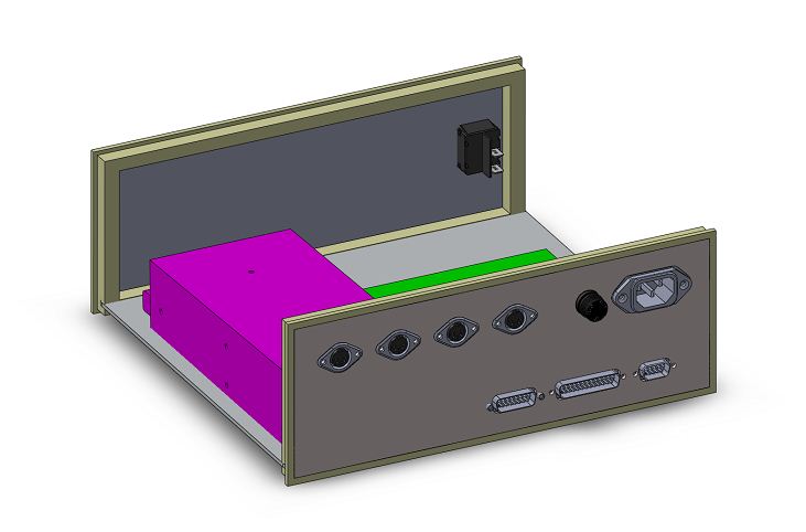
When it came to the rear panel layout I did use CAD software, as I wanted the connectors to spaced evenly and I needed to make sure I had room to run the wiring. Again, I printed a 1:1 scale drawing with the cutouts and screw holes marked, and traced that onto the rear panel.

controller rear controller inside

A step drill made quick work of the holes for the circular DIN connectors and AC input fuse.

IMG_4426

The remainder of the cutouts were made on the mill.

IMG_4428 IMG_4431

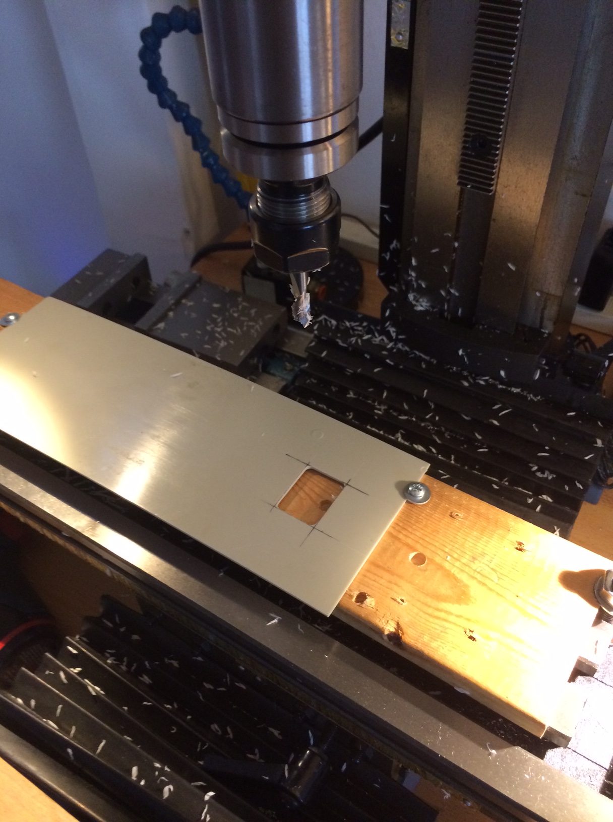
A sharp utility knife squared off the corners of this cutout for the power switch on the front panel.

IMG_4433

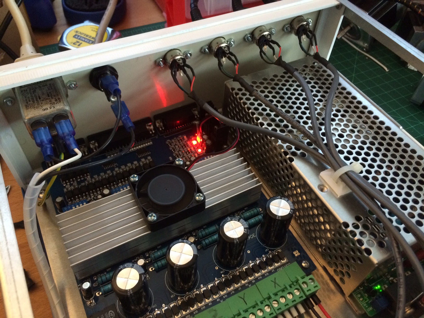
Skipping forward a few steps, the AC input connector and fuse has been installed and wired to the front power switch and power supply.

IMG_4434

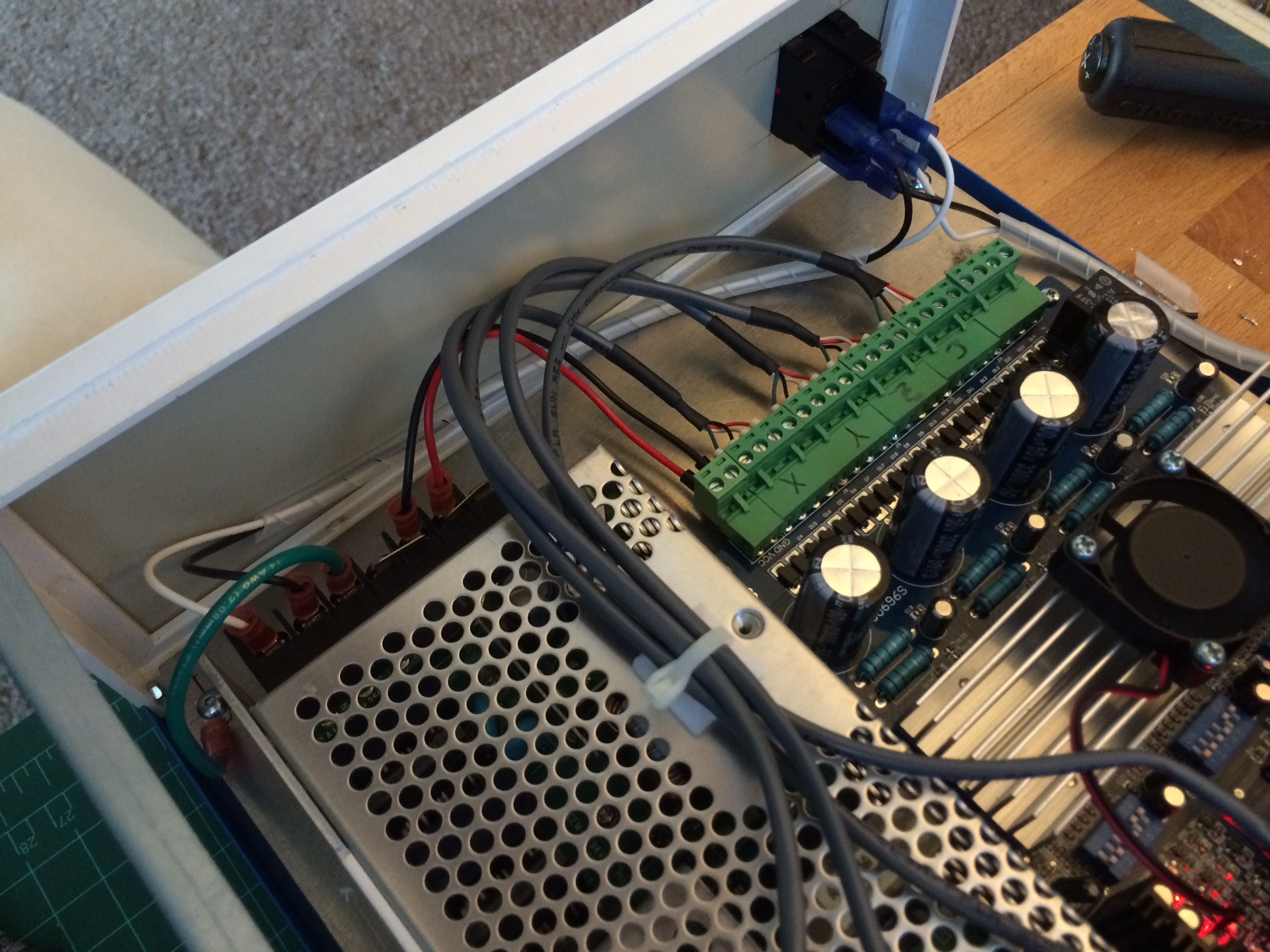
I used 4 wire 22 gauge shielded security system cable from McMaster to make the internal connections from the driver board to the DIN connectors. Where the wires connect to the Phoenix connectors (also called Euroblocks, those green pluggable screw terminal connectors) I terminated the wires with wire ferrules and heat shrink over the cable covering.

IMG_4416

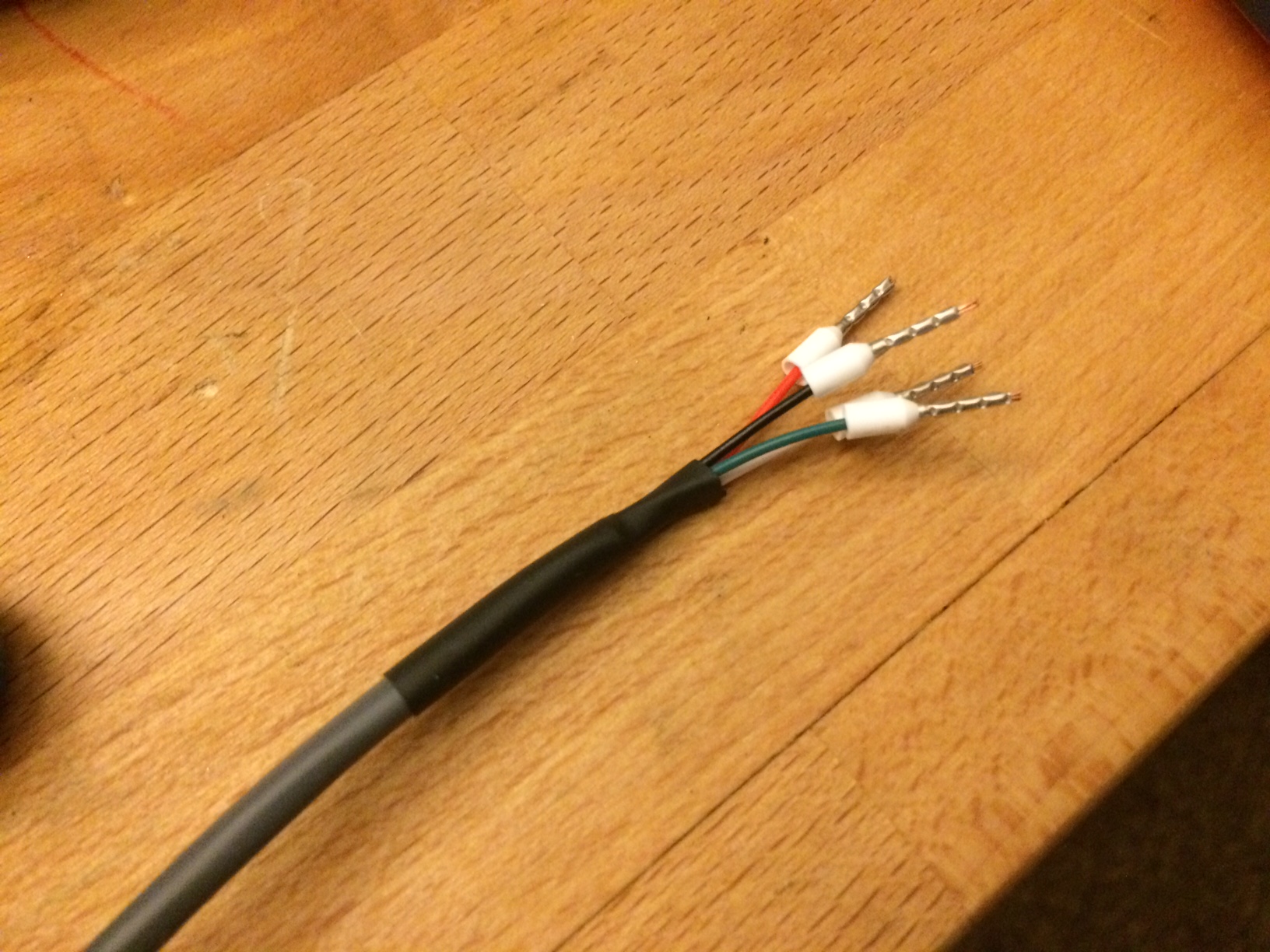
Using wire ferrules instead of bare stranded wire in a screw terminal is good practice, as the strands of wire tend to get broken in screw terminals, increasing the contact resistance.

If you’d like to learn more than you ever probably wanted to about wire ferrules and their use, see this white paper from Weidmuller.

IMG_4435

IMG_4436

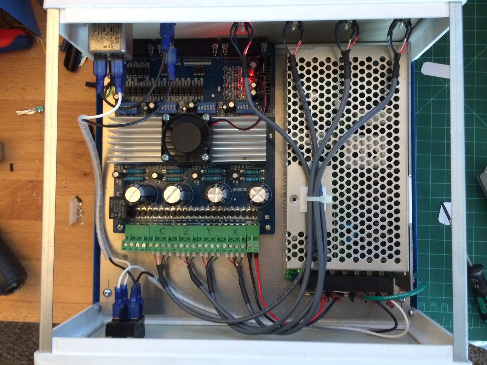
A cable tie mount on the power supply neatly bundles the stepper motor cables.

IMG_4437

One last overall shot

IMG_4438

At this point I thought I was done. However, my decision to use the 4 axis all-in-one board was bugging me. It’s known to be buggy, and if one axis blew the board could be taken out entirely. In the name of making a more robust driver, I switched to individual axis drivers and a break out board.

513su4LQ-GL

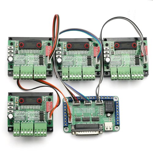
The breakout board was pretty easy to mount. 4-40 self tapping screws and nylon spacers secured the board to the enclosure panel. The individual drivers where more challenging. There wasn’t enough room to lay them flat, which meant they need to be mounted on the edge of their heat sink. I thought about a few ways to mount them (screws coming up from the bottom, adhesive, pieces of all thread) before I came up with the idea of using a small strap through the heat sink fin.

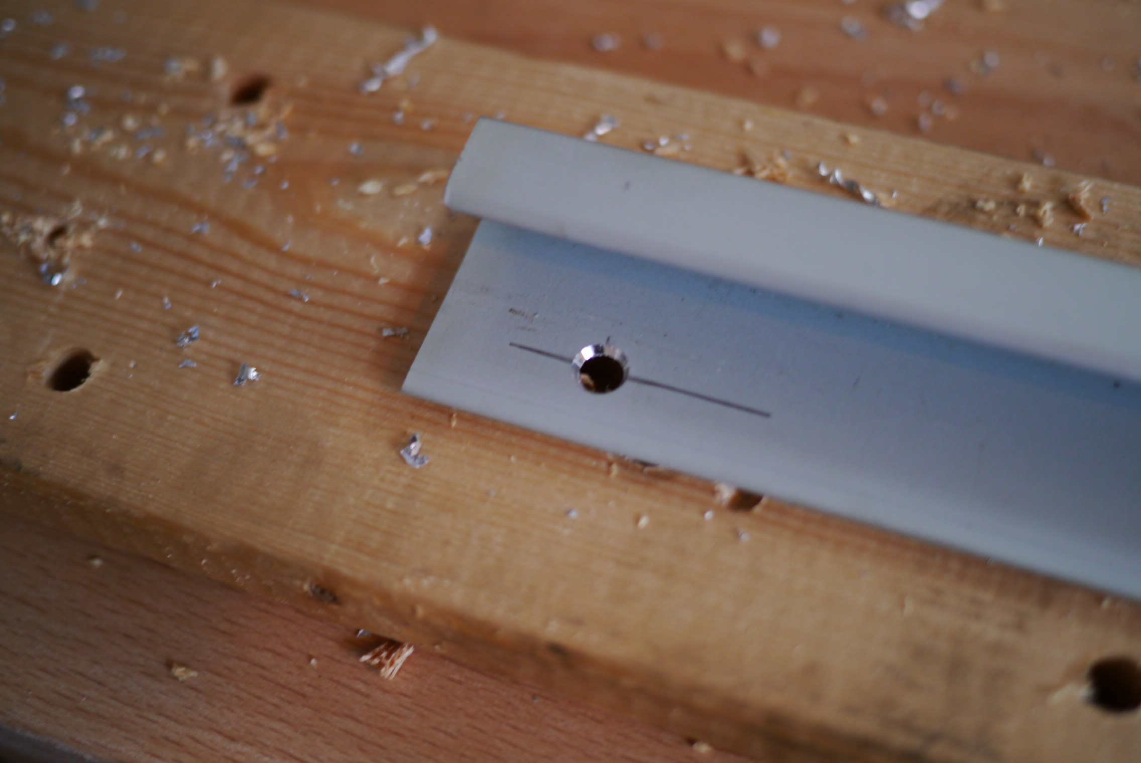
Using the same 0.090″ aluminum, I machined some 3/8″x4″ straps, with 1/8″ holes for 4-40 hardware.

IMG_4463
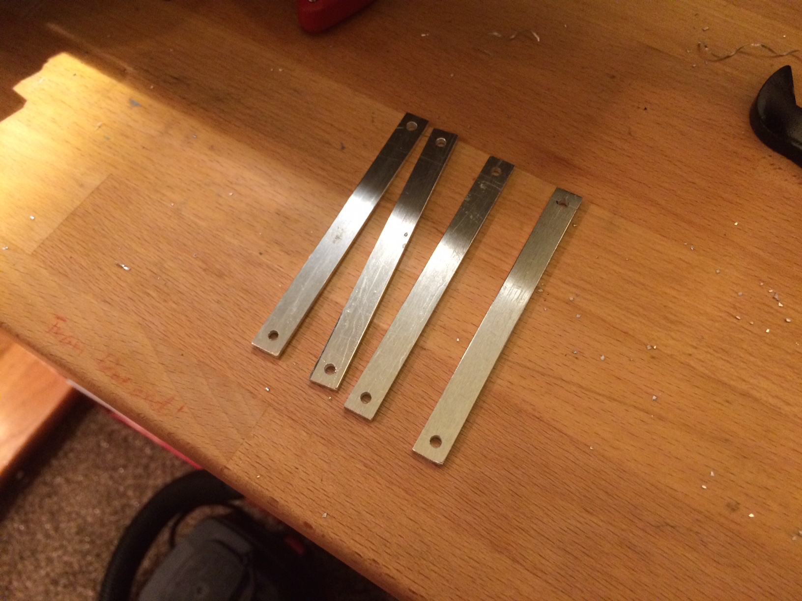
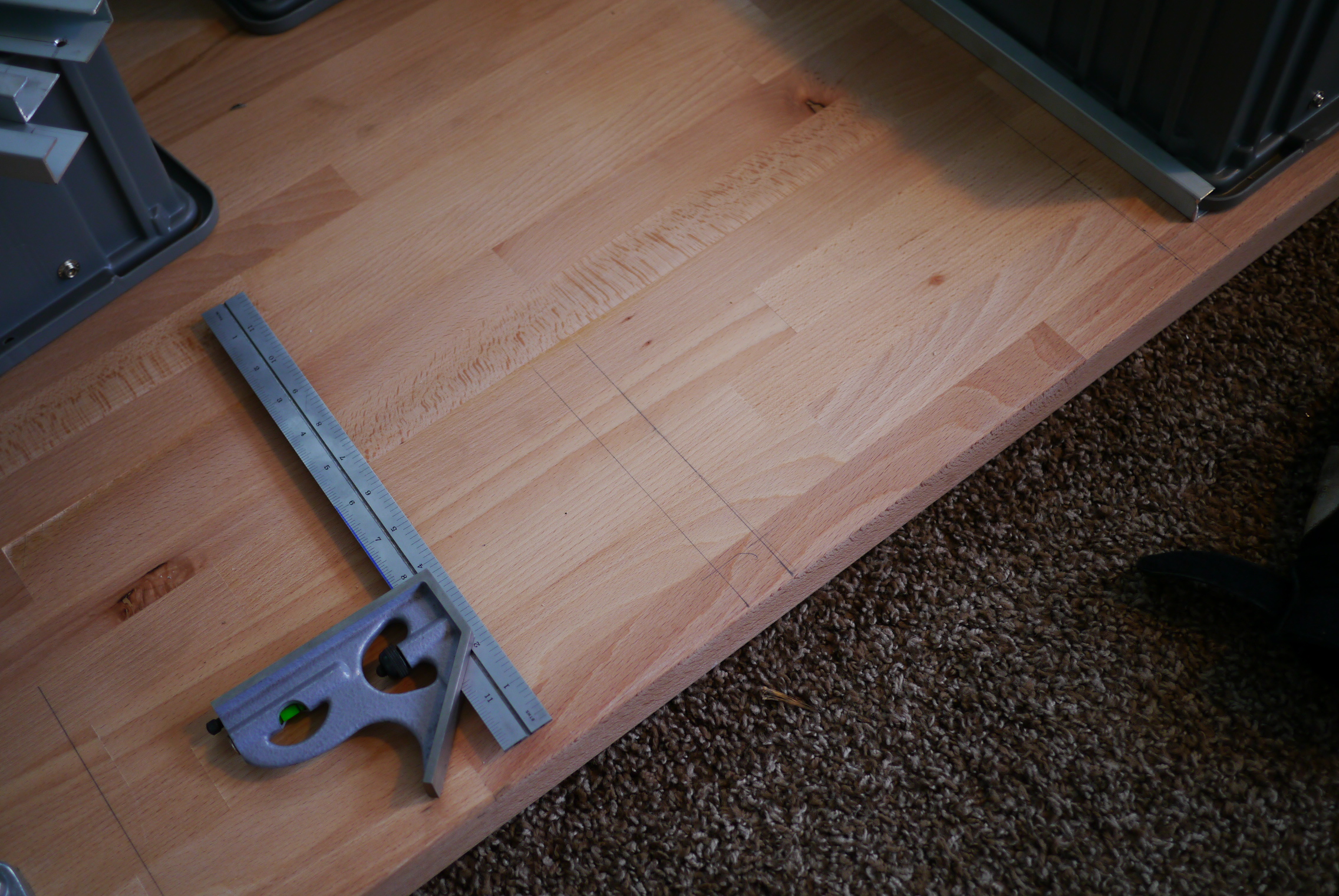
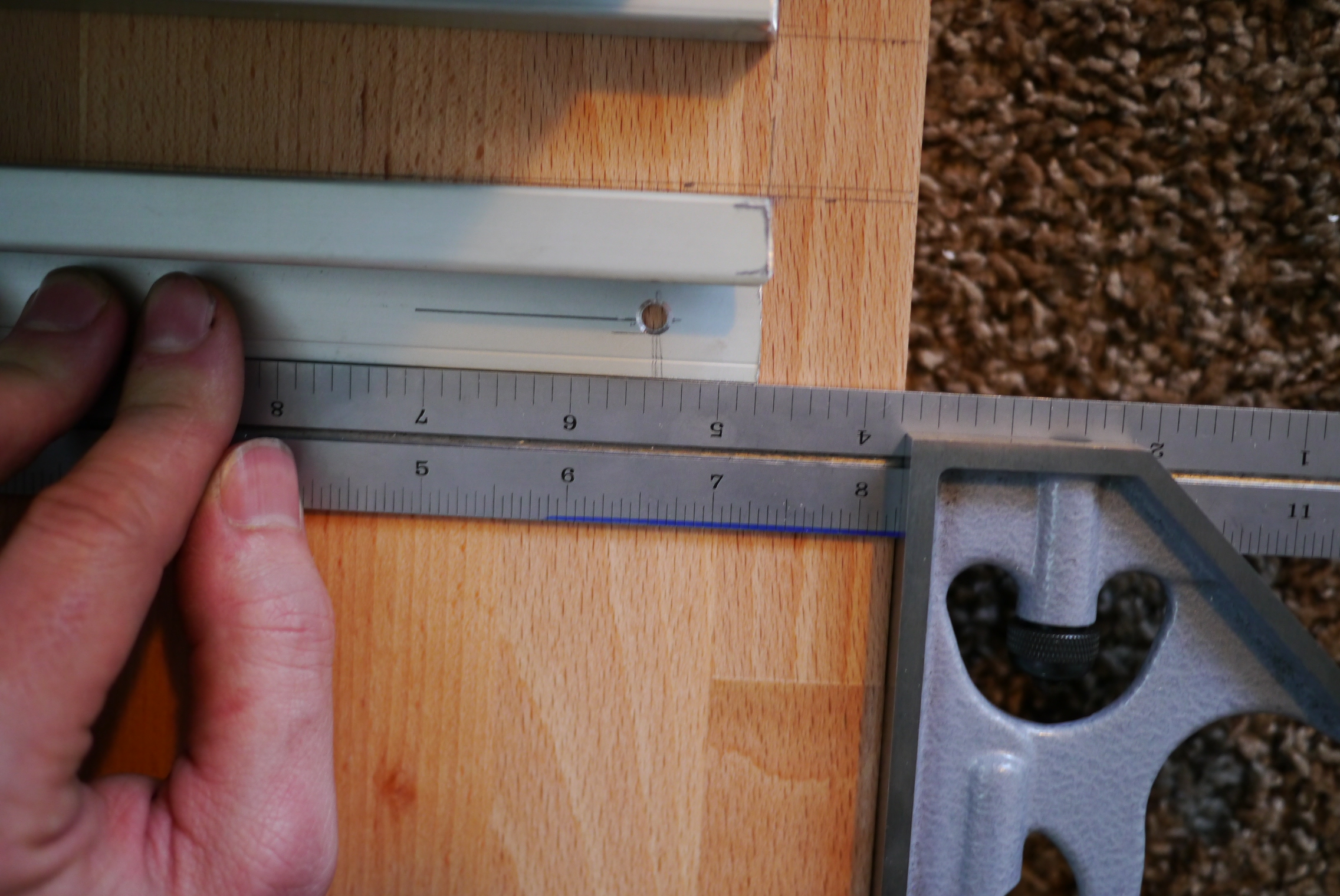
Laying out a hole pattern to space the drivers on a 2″ pitch.
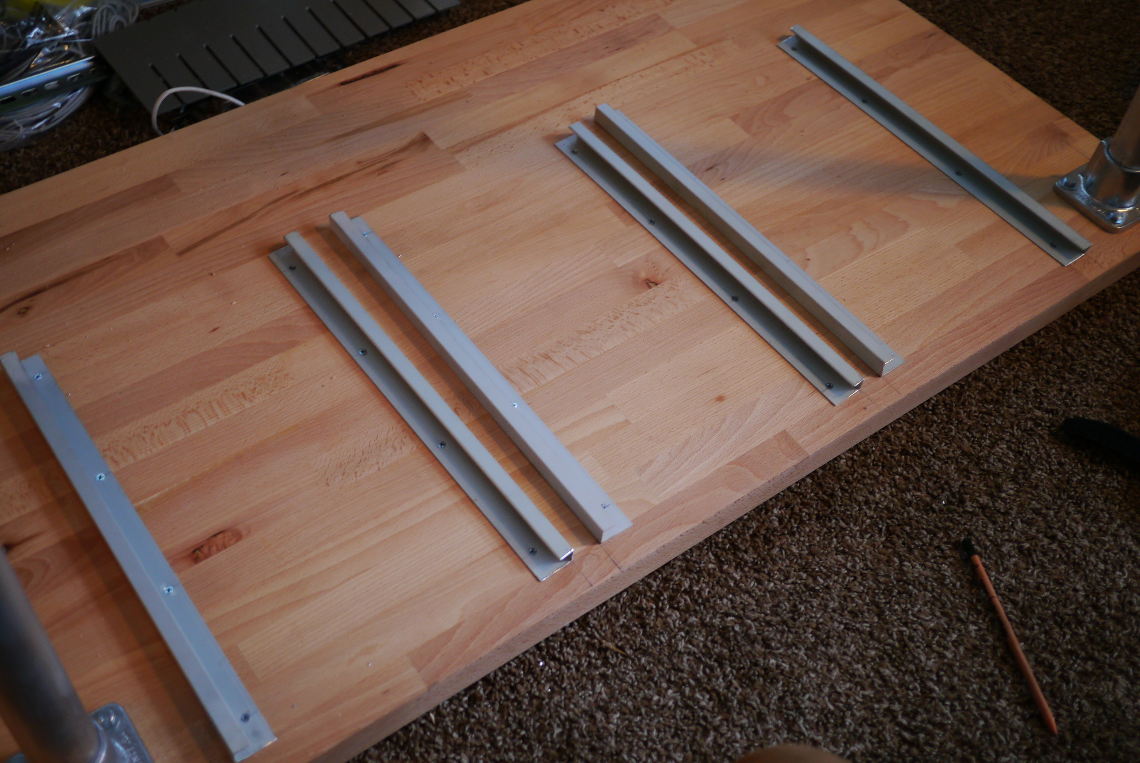
IMG_4464

First test fit.

IMG_4466

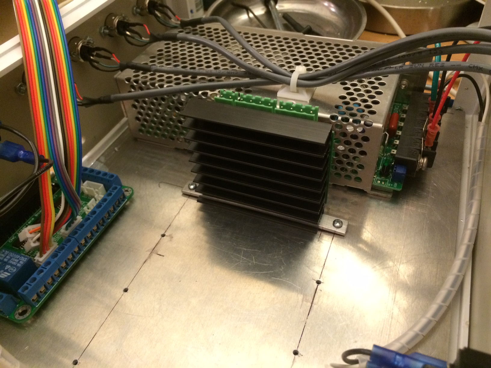
Success! The driver is firmly attached, and most importantly, I can remove the driver easily if I need to change setting on the DIP switches. An added bonus is that the heat sink can conduct some of its heat away to the aluminum panel beneath it.

Fortunately the wiring I had made previously for the stepper outputs fit fine, so those did not have to be remade.

IMG_4467

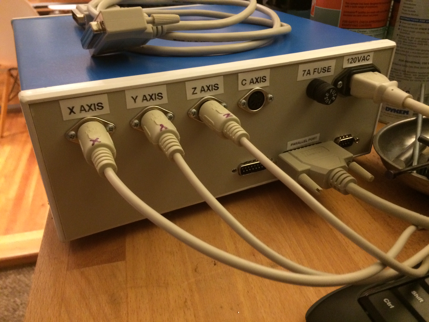
Some labels on the back finish the driver box off.

IMG_4443

IMG_4444

Advertisement

The Apartment Workshop Series: Workbench

Due to a job change I no longer have access to the plethora of tools at my old job.  While there are some local hackerspaces, I really like having access to equipment whenever inspiration strikes, rather than having to wait unil the hackerspace is open (also working in your boxers on a Saturday morning). So I am setting up a small workshop in my apartment living room, were I plan to do everything from soldering to machining. This will be the first in a series of articles showing how I setup  and fill this space with various toys.

Every good work shop starts with a good workbench. My money-is-no-object bench would be a Lista cabinet with a maple butcher block top.

18733s3.tifUnfortunately these are disgustingly expensive when bought new and, unless you get lucky on craigslist or an auction, they are still expensive used. My goal is to replicate the Lista bench, but for an order of magnitude cheaper.

One of the first things you should do when designing a workbench is to think hard about what you will actually be using it for. A bench designed for SMT electrical work is a lot different than one for taking engines apart. I plan to use my bench for tool storage, some soldering/electronics, parts storage, machining (once I get a small mill and lathe), light assembly, and taking things apart. I took each of those tasks and figured out what requirements they would impose on my design.t

For tool storage (specifically, hand tools) the Lista cabinets are great as the many thin drawers allow for an enormous amount of storage in a small footprint. Lista cabinets are very similar to rolling tool carts found in garage shops (minus the caster wheels), so that’s where I started looking. I spent several hours researching rolling tool carts on garage journal and reached several conclusions. If you’ve got the money, tool truck boxes (snap on, matco, etc) are hard to beat. They offer the best construction, but at a hefty price tag. Surprisingly, Craftsman tool boxes were generally regarded as the worst quality, people described them as having thin gauge sheet metal, and really bad drawer slides. Also surprisingly, Harbor Freight tool boxes were said to be the best tool box for your money, decent quality, but still affordable.

I ended up getting Harbor Freight item#67831 and selling off the top box to recover some funds. Make sure you get the 26″ model, the brownish 30″ one is much lower quality.

With the tool storage figured out I started looking for a work surface. I like working on wood, as I can sand down and refinish it when it becomes too loaded up with crud (it also looks nice). I went looking for a low cost alternative for the maple top on the Lista bench, and found the Numerar series countertops from Ikea.

It isn’t as deep as I’d like (25″), but the construction (almost 1.5″ thick beech!) and price were spot on. I ended up getting the longer 96″ version, figuring I could always trim it down and use the extra as a lower shelf.

Next up were finding sturdy legs. I considered using wood 4×4 posts, but since this is in my living room and very visible, I wanted it to look a little nicer. I chose speed rail fittings and 1 1/4″ sch 40 aluminum pipe, as they are very strong, but gave it a slightly industrial look. I later found out that McMaster has a nice selection of pre made work bench legs, some with cut outs for electrical outlets.

4885tp1l

For medium sized parts storage I wanted to utilize the area under the work surface by hanging pull out drawers. Since I don’t have access to a cabinet shop to make custom drawers, I came up with my own solution. In my experience work bench drawers usually end up as a disorganized pile of random parts you don’t know what else to do with. Since the drawers are just one large space everything ends up mixing together.

b1a05683-c3be-4c92-b979-dd5af61465e2

My solutions to this was bins with a divider grid system. These bins are dividable down to spaces 1″x1″, allowing for the creation of all sort of odd sides compartments. They also come in a variety of depths and colors, and are stackable.

The drawers slides ended up being one of the harder problems to solve. How do I hang these bins on the under side of the work surface? They have a large lip, and sloped sides so I couldn’t just attach off the self drawer slides. I considered building a self underneath that they could rest on, but interfacing with the speed rail was problematic. I really needed a bracket that the bins could slide on, supported by the lip that runs along the outside. If you know machine tools think of it like box ways. I initially thought about making my own from aluminum square tubing, but that would have been a lot of machining time to cut all the slots and holes (I needed to make about 8-10 slides).

I was browsing McMaster one day and found this aluminum extrusion that is normally used as trim around panels. It has the perfect shape to function as a slide, but still allow me to have a spot to screw it to the underside of the bench.

8427a52p1-j06l

With all the parts acquired I could start putting it all together. I first layer out the hole pattern for the leg fittings, insetting them slightly for appearance.

P1020327

3/16″ clearance hole for a 1/4″ lag bolt.

P1020328

The drawer slides came next, I drilled and counter sunk holes for  #8 wood screws. I had to counter sink them as the drawer would hit any fastener proud of the surface when pulled out.

P1020329

P1020331

P1020332

Aligning and spacing all the slides.

P1020333

P1020337

P1020338

Here’s the almost finished bench. I put on several coats of tung oil to act as a sealer, turning it a golden color. After this was taken I also added an additional leg in the center towards the front, as it needed a little more support mid-span.

P1020346

P1020345

I ended up using the full length of the counter top material since it fit in the space and you can never have enough work surface.

If you’re curious here’s a few shots of the drawers filled with parts.

P1020456 P1020455 P1020451

Modern Dining Table Part 3: The Conclusion

Part 1 and Part 2 here.

This weekend I wrapped up my modern dining room table project by installing the legs. Rather than 4 individual legs, I chose two trapezoid shaped metal frames on each end.

photo (16)

This table won’t have an apron, which gives rigidity to a table. Think of the point where the table attaches to the legs as a hinge. The further away from the hinge that the leg is supported the more rigid the connection, so apron = good, stretcher = better.

With a leg configuration like I have you’d normally need a stretcher between the legs to prevent the table from wobbling side to side.

Screen Shot 2013-10-06 at Oct 6 5.00.34 PM

How to make a stable table. able.

To eliminate the need for a stretcher, the flanges where the top connects to the legs were made extra wide by adding a piece of 3/16″ angle to the steel tubing.  1/4″ lag bolts secure the legs to the top (pre-drill so you don’t split the wood!)

P1010785

I wanted some contrast between the legs and the warm natural look of the reclaimed wood table top. Rather than paint the legs I had them clear coated, allowing the welds and tube seams to show through.

P1010791 P1010793

I need to put some felt pads under the legs to protect the floor, but other than that I’m going to call this one done.

Suppliers:

Wood table top: http://www.americanmaad.com/tables

Legs: http://www.etsy.com/shop/TRRTRY

Sealing it

With the melt tank installed and the pump body assembled, I can now start fitting the injection cylinder to the tank. The large (50mm!) air cylinder moves a piston in the pump body to draw in molten plastic, and then force it into the mold cavity. The piston seals to the pump body with a cup seal. The original mold-a-rama actually has no seal on the piston itself, it seals around the shaft of the injection cylinder, the seal can be seen here:

DSCF5337

This is the injection ram of the mold-a-rama. The seal is in the center of the picture on the aluminum plate, the fiberglass insulation is covering the tank.

Installing the seal was a real bear. The cup seal is sized for a 3″ cylinder, it flares out to ~3.25″ OD to press against the cylinder walls. I needed to compress is to fit it into the cylinder. Softening the seal really had no impact on it’s flexibility, what I really needed was a piston ring compressor. Lacking that I used several daisy chained cable ties. That still didn’t work well so I used some plastic tools to push the seal in.

IMG_0290

I wasn’t sure what to use to insulate the melt tank until a fateful trip to Lowes. In the pipe insulation section I found this self-adhesive aluminum foil backed foam tape. The adhesive holds up to the tank temperatures, and the heat radiating off the tank is noticeable reduced (as measured using the calibrated portion of the back of my hand).

IMG_0292

I looked long and hard for a plastic water tank that was compact, but had a large enough opening to fit the water pump through. The water pump is supposed to be submerged in the water tank, this  will extend the pump life by keeping it cooler. I gave up on finding a plastic tank and made a metal one myself. The body is made from 6″x6″x.120″ wall aluminum tubing with a water jet aluminum flange and lid. A cable gland seals around the power cable. The gold cylinders sticking out from the flange are rivnuts, those along with thumb screws will allow tool-less removal of the water tank  lid for refills. I plan to add a sight glass later on so I can check the water level with out removing the lid.

IMG_0712

The mount for the mold delivery cylinder (the one that pushes the finished plastic part into the retrieval bin) is made from a small piece of 1″x3″ aluminum tubing welded to the top frame and a shaft collar.

IMG_0713

The lower half of the aluminum shaft collar is welded to the back of the rectangular tubing, the upper half is free  and is what clamps onto the cylinder.

IMG_0714

The molder is pretty awkward to move around as it doesn’t sit on a wheeled base. I added handles to each side to make moving it a little easier. The first set of handles I got from McMaster were plastic, thinking the machine couldn’t weight more than 100-150lbs, it turns out I forgot to take into account two very heavy items: the water chiller and the compressor. After putting those in, the machine weights closer to 200lbs. The plastic handles were quickly swapped out for some beefy aluminum ones. I’ll still probably move the machine with the compressor and chiller removed, but now I have a lot move confidence in the handles while moving the machine.

IMG_0717

And finally, before I go, a sneak peak of the new molds!

IMG_0725

Build Blitz Weekend 1

With the deadline for complete rapidly approaching, progress has stepped up. I spent most of my Saturday machining, welding, and cutting.

The bottom of the main valve on top of the injection cylinder has pipe threads to accept a compression fitting. One note about pipe tap, you need to be really careful about your tap depth. If you tap too deep with a tapered pipe tap you can end up in a situation where your fitting bottoms out before the threads tighten up, leaving you with a leaky pipe connection. So pay attention to that thread call out and test with a fitting if you are unsure.

IMG_0261

Here are all the parts for the injector valve assembly. This regulates the flow of plastic and air into the mold cavity via the shuttle valve sliding back and forth.

IMG_0262

Starting hole layout for the melt tank. I kind of wish I had used steel for the tank instead of stainless steel. Stainless is a real pain to work with. It’s hard to cut, hard to drill, hard to bend, hard to weld. Just really unfriendly in general. The original mold-a-ramas used an aluminum tank, but I got a really good deal on the stainless tank I started with to make this part.

IMG_0263

Another area where I’m differing from the original mold-a-ramas is the piston design. The original injection cylinder sealed agains the rod of the hydraulic cylinder used to inject plastic for the melt tank to the mold. In my design I have the seal on the piston. I’m very nervous excited to see how well this works. There is another disk, not shown, that will retain the seal against this piston.

IMG_0264 IMG_0265 IMG_0266


A few more from this weekend:

IMG_0267

I really need to hire a hand model.

IMG_0268


There are a few more bits and pieces that need to be fabricated (frame for cover, water tank, brackets for a few items), but the bulk of it is done. Next up is programming, wiring, and test/debug.

Mold-A-Rama Build Begins

I have spent the last 5 months designing, buying parts, redesigning, and buying more parts. I am finally at the point of cutting metal and bolting stuff together (the fun part). I have to say, it feels pretty good. Below you can see the 80/20 frame (mostly 1010 series with a lower frame made from 1020 series extrusion) , it is still missing a few crossbars near the top, as I hadn’t yet tapped the ends of the extrusion to accept a corner fitting.

I was initially concerned about how rigid the 1010 uprights would be given that the they are only attached to the bottom 1020 frame with two plates each. I found that it holds up surprisingly well to small amounts of force (hand applied), and this is even without the aluminum weldment that fills the space between the two angled bars. You can also just barely make out the waterjet cut 120 degree brackets on the front angle.

photo (12)

No longer just shapes on a computer screen.

I’m also very close to some initial tests with the pneumatics. I have new sensors for air cylinders that interface better with a micro controller, and have started breadboarding the transistors to drive the solenoids valves.

DIY Mold-A-Rama Update 3

A lot of progress has been made in the last few months on my version of the 1960’s classic Mold-a-Rama machine.

The design has been further refined

  • The frame where the mold cylinders attach has been changed from 80/20 to 1″ square aluminum tubing.
    • This change was made because I was having a hard time mounting and aligning the various components to the slots in the aluminum extrusion.
    • The mold halves will press against each other with several hundred pounds of force; the friction fit nature of t-slot construction would likely have failed under this load. The new frame is a one piece welded structure.
    • The new frame, while not re-configurable, will be much stronger and allow for easier alignment of the plastic tank and mold halves.

overview_2_15_13

  • The plastic pump has been completely redesigned
    • I’ve switched from a right angle gear motor to an air cylinder driven piston pump (think giant aluminum syringe)
    • This change eliminated a complex machined part ($$$) and replaced it with a much simpler welded tube and plate design ($)

melt pot complete_2_15_13

  • The actual mold cylinders have been selected
    • So much of the design decisions and components selections have been driven by what I can get on the surplus market  Case in point: the mold cylinders. I’ve seen that the actual mold-a-ramas have an enormous amount of play in their mold cylinders and mounts. I thought using a twin piston cylinder would help with the side loading on the pistons (due to the weight of the molds want to slide down on the angled frame. I found a good price for two twin piston SMC cylinder on eBay (with sensors and flow control fittings!)
    • I designed a robust mounting system using aluminum tube, bronze bearings, and 5/8″ steel shafting.

mold cylinders_2_13_15


Parts have been bought

I’ve also been spending quality time on eBay, at surplus stores, and throwing money at various other online retailers. Here’s where some of the money has gone:

photo 2

Left to right: Air compressor, air tank, compressor switch

The air compressor is a Thomas & betts unit I got at C&H surplus (super cool store, check it out if you’re in SoCal). It has twin cylinders and puts out more CFM at a lower decibel than most compact air compressors.

photo 3

Left to right: water pump, auger for plastic hopper, cartridge heaters

photo 1

The top two cylinders move the mold halves together, the bottom one moves the piston in the plastic injector, and the solenoid manifold on the right controls it all.

photo 4

50lbs of hard to find plastic

The ability to buy the plastic pellets was a make or break moment for this project. There were not a whole lot of suitable replacements for this particular plastic (more specifically, polyethylene wax). Fortunately the west coast distributor for this happened to be close and had several bags it was willing to sell to me (normally this product only sold in 1000kg pallets, which is about 950kg more than I need). Getting a hold of this was a major load off my mind.

BA6JS4JCcAAwIJm

It’s like the warehouse in Indiana Jones, but instead of ancient relics there’s plastic resin.

I’ve begun cutting metal for the frame and plastic melt pot, hopefully welding will start this week!

Cardboard Mockup: The Original Rapid Prototyping

I often find it hard to get a sense of scale when designing things using CAD software. Staring at a model on a 24″ screen can sometimes make small objects look massive, and large objects tiny. Placing  references (such as a person) next to your model helps some, and there are many free human models for pretty much all CAD platforms. However nothing beats a physical prototype. If your part is small enough 3D printers are perfect. For larger parts you have to get creative. The final frame will be made of 80/20 aluminum framing, but I did not want to commit to cutting it up just yet, as I was still playing with the frame dimensions. I needed a cheap material that was easily formable, yet sturdy enough to hold its own weight, next to my door was the answer: double wall cardboard.

Just as architects use cardboard to construct scaled down buildings, I built a 1:1 model of my mold-a-rama replica. Using only packing tape and cardboard, I was able to quickly (and cheaply) build a model that’s accurate to about 0.25″.

I started by measuring the outside dimensions of my model in solidworks, and transferring those to cardboard. Here’s some tips I learned from doing it:

  • The boxes I had on hand were medium to small-sized, with fold lines all over. If you can’t cut around the lines, take another piece of cardboard and tape it over the fold line to reinforce it.
  • Reinforce the corners by making a long  L-bracket and tape it to the inside.
  • Cardboard tabs can be used to prop up unsupported spans of cardboard.
  • Get some good blades for your utility knife, I like Irwin bimetal blades. They make cutting through thick double wall cardboard a breeze.

And here’s the end result:

Cardboard mockup

Those 3rd grade arts and craft skills are finally paying off.

As I suspected it was bigger in full-scale than what I thought it would have been.

Another benefit is that the interior volume is very close to the usable space inside the actual machine. I was able to place most of the bulkier components inside, allowing me to play with layout:

Interior layout

From left to right: air compressor, injection cylinder, plastic melt tank, water pump (blue thing peeking out), water chiller.

Moving components around inside the cardboard model was so much faster than doing it in CAD. It also gave me a better idea of how much space I need between components.

The layout above is mostly complete. I have since gotten an air tank that sits in the back left corner. The stainless box you see is the starting point for the plastic melt tank (I’ll go into more detail in the next post where I’ll show off some of the components  that have already been bought)

This method really only works if what you are building is mostly flat panels that meet at right angles. If you’ve got a contoured model and you are set on using cardboard, make an STL file of your part with layers that match your cardboard thickness and print out patterns. This can be done using the free software AutoCad 123D (http://www.123dapp.com/make)

Modern Dining Table: Part 1

I’ve started designing a dining table for our new apartment. I really like the aesthetic of reclaimed wood and steel tables, unfortunately a pre-made table like this costs in the $1500 to $3000 range. Way more than I can spend on a table. The designs are very simple and I figured I could make one myself. After some digging I found a local shop that will build the table top out of reclaimed douglas fir. The legs are designed by me and will be either made by myself (pending purchase of a TIG welder) or will be sub-contracted to a fabrication shop.

Continue reading

Automated Piston Cycler Device with Arduino

I built this control box to cycle a piston in some of our assemblies at work. We had problems with rebuilt assemblies sticking after a few hours of cycling. The rebuilders couldn’t test this because they would have to manually cycled the piston back and forth many times to verify the functionality (time-consuming). This piston cycler is capable of automatically cycling a dual action cylinder at an adjustable rate, and enable the operator to pause the motion to make adjustments, and continue testing. The counter keeps track of the number of cycles for record keeping purposes. Here’s how I made it.

Continue reading