Over Center, Under Pressure

One of the ways the mold-a-rama process differs from traditional injection molding is the way the part is ejected from the mold. Usually one of the dies has a set of ejector pins that pop the part out of the mold (if you look at most plastic products you will see a series of small circular or square indentations on the back side, these are small marks left from when the ejector pin pressed the part out of the mold.) In this lego manufacturing video you can see the thin ejector pins stick out right as the part falls out of the mold at the 40sec mark.

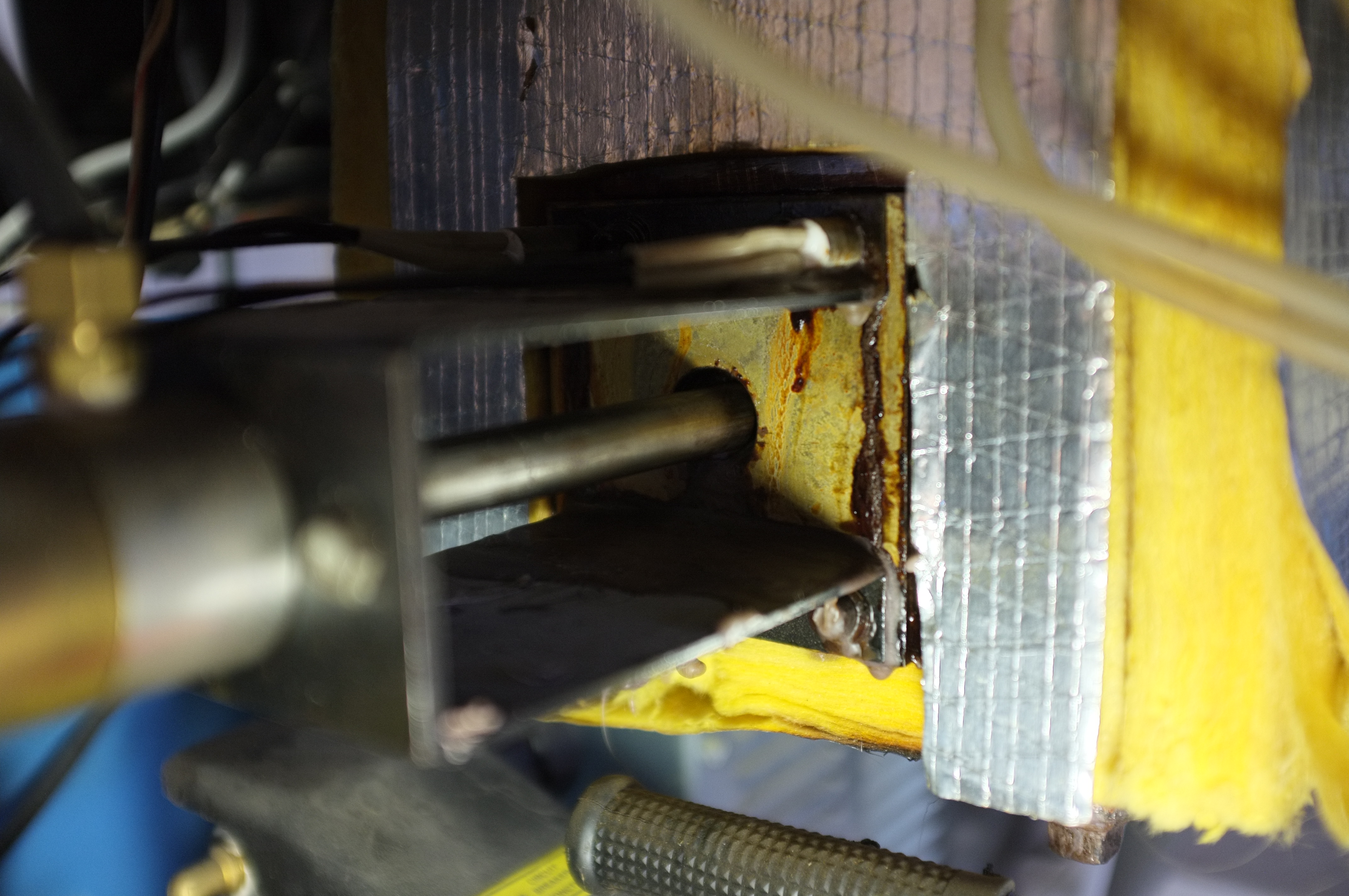
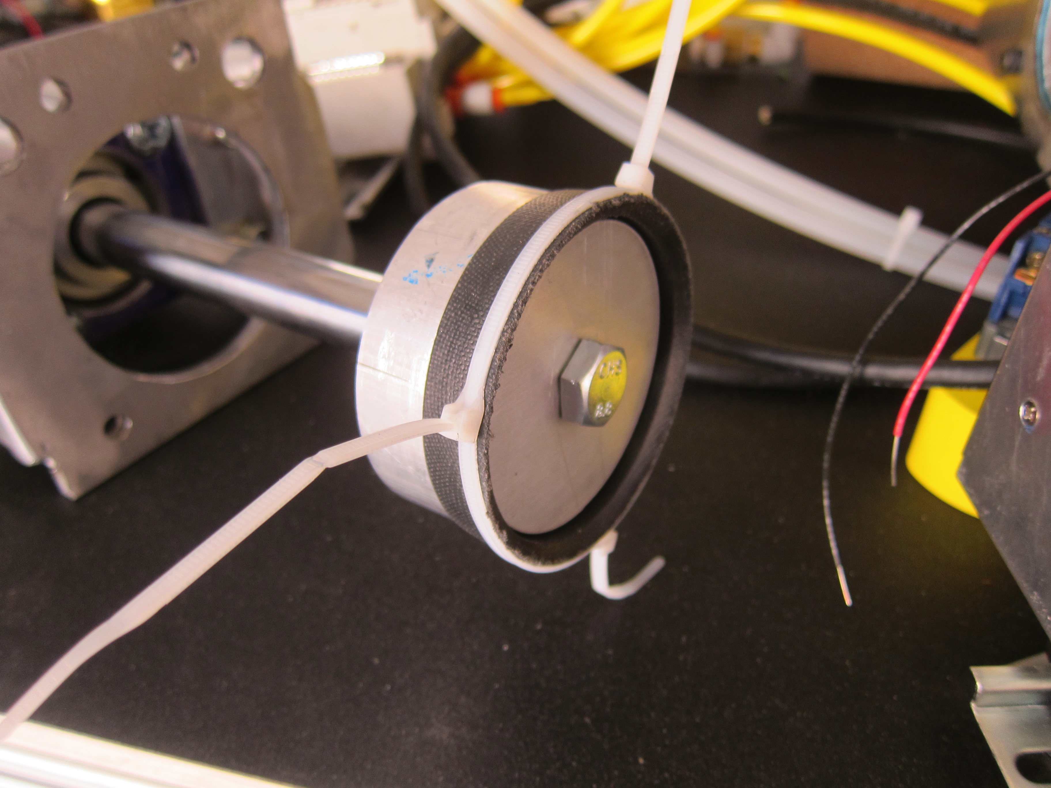
To keep the machine simple, the mold-a-rama uses no ejector pins. Instead it relies on the part staying in place while the molds open around it. This is possible because the bottom of mold-a-rama die is actually open. This is a picture of the bottom of my mold dies.

Bottom of Molds

The base of the plastic part sticks to the tank lid (which is why all mold-a-rama toys have some kind of flat base.) Traditional injection molding dies form a sealed cavity when they meet, save for the sprue, the opening where plastic enters the mold. Mold-a-rama dies form a complete cavity by sealing against the melt tank lid (the aluminum square below the molds, which also serves as a cover for the plastic melting tank). As you can imagine, it is very important that the dies press firmly against the melt tank lid, otherwise plastic would leak out between the dies and the tank lid.

Below is a CAD screenshot of the mold cylinder assembly I originally made, the die is the blue rectangle. Can you guess if they functioned correctly?

overcenter_cyl_mount

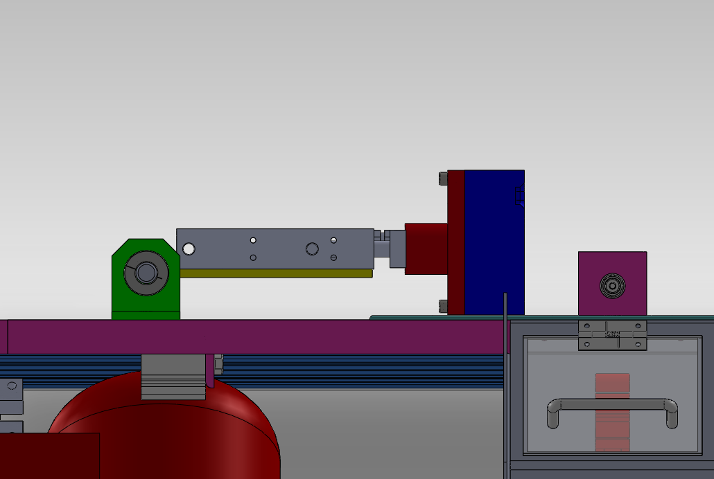
The answer is no, no they did not. When the dies closed against each other they popped up slightly, instead of being forced downward to seal against the melt tank. The can been seen in the video below. Watch towards the end and you will see the pair of molds raise up slightly.


If I were to run this in an injection cycle I would have melted plastic spewing out.  After some head scratching I realized I had the mold cylinders (the grey rectangular part in the CAD screen shot) placed above the pivot point (the grey circular part), this meant that when the molds pressed against each other it tended to rotate the entire mold cylinder and mold counter clockwise about the pivot point, which meant the mold moved in the upwards direction. I tested this theory by flipping the entire mold cylinder and mount upside down. Now the mold cylinder was below the pivot point, which meant the mold cylinder now tended to rotate clockwise about the pivot point, forcing the die downward. This video shows how the molds are forced downward when they meet.


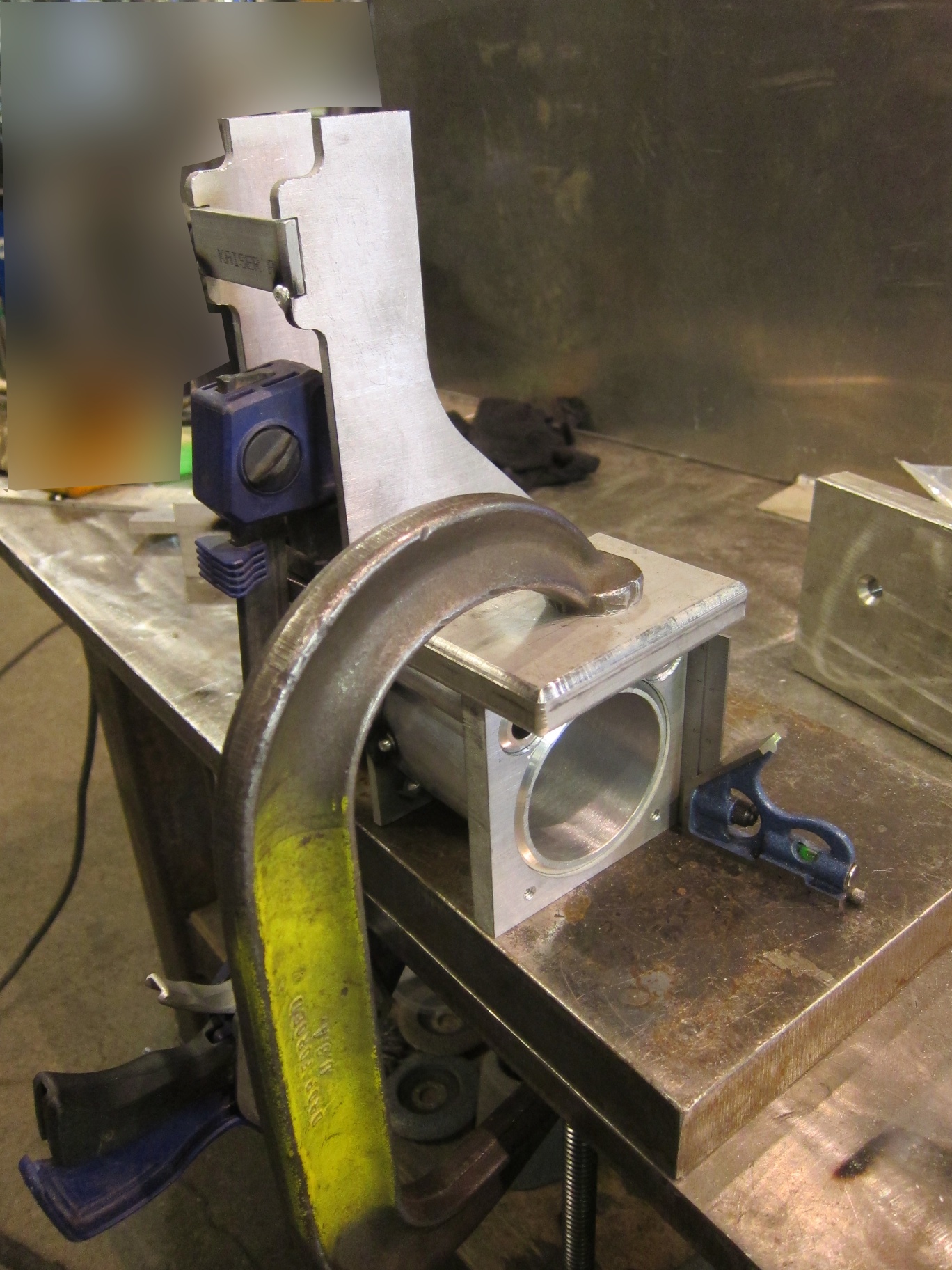
Armed with this realization, I redesigned the mold cylinder mounts to match the flipped version I had tested. With the two designs side by side (old on left, new on right) you can see how the mold cylinder location has changed relative to the pivot point.

compare_mounts

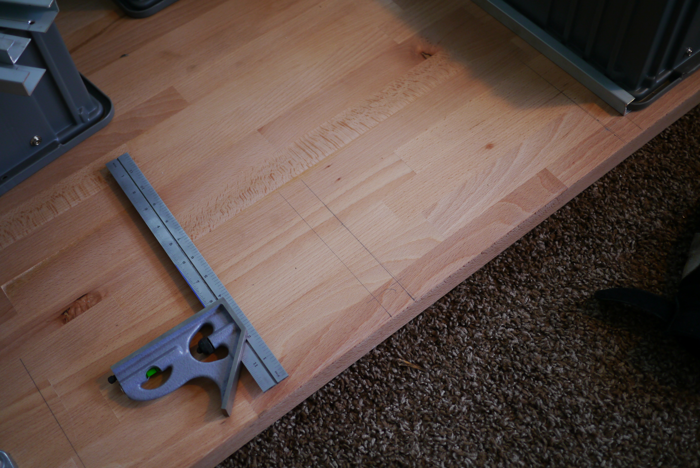
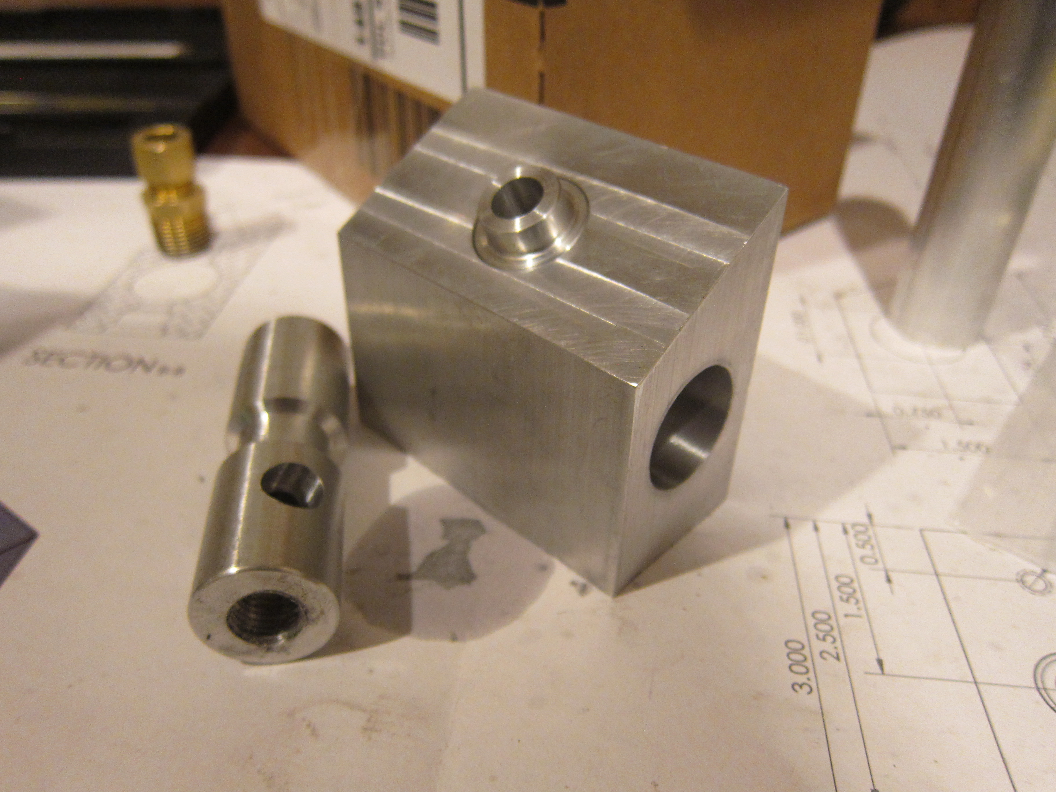
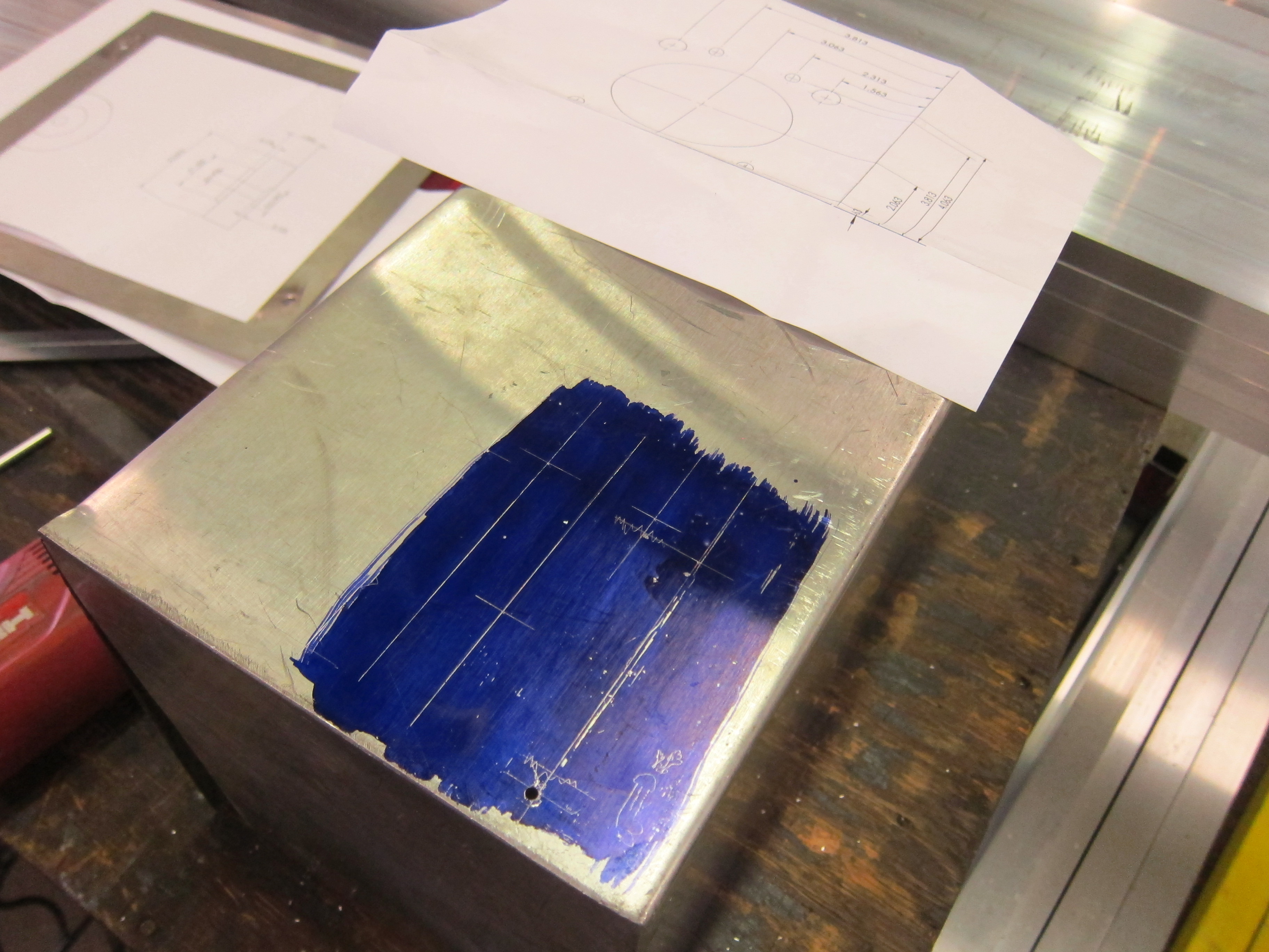
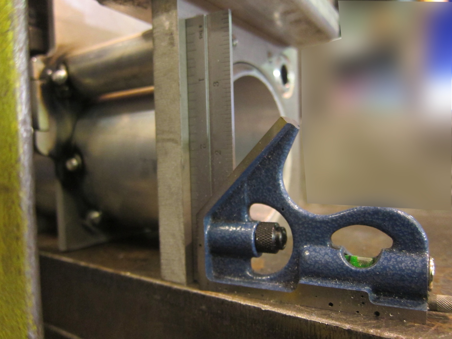
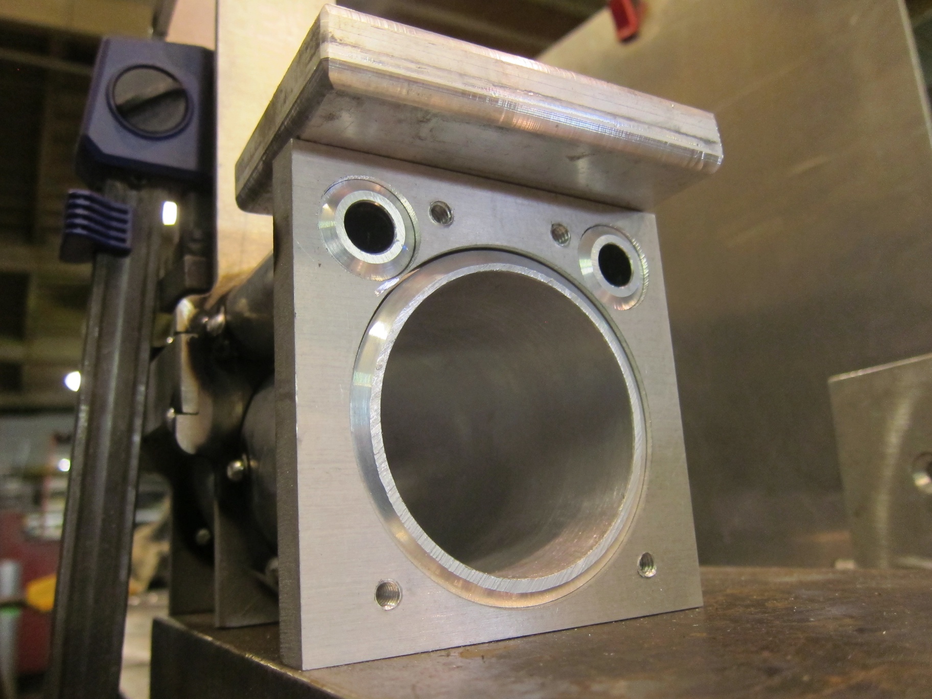
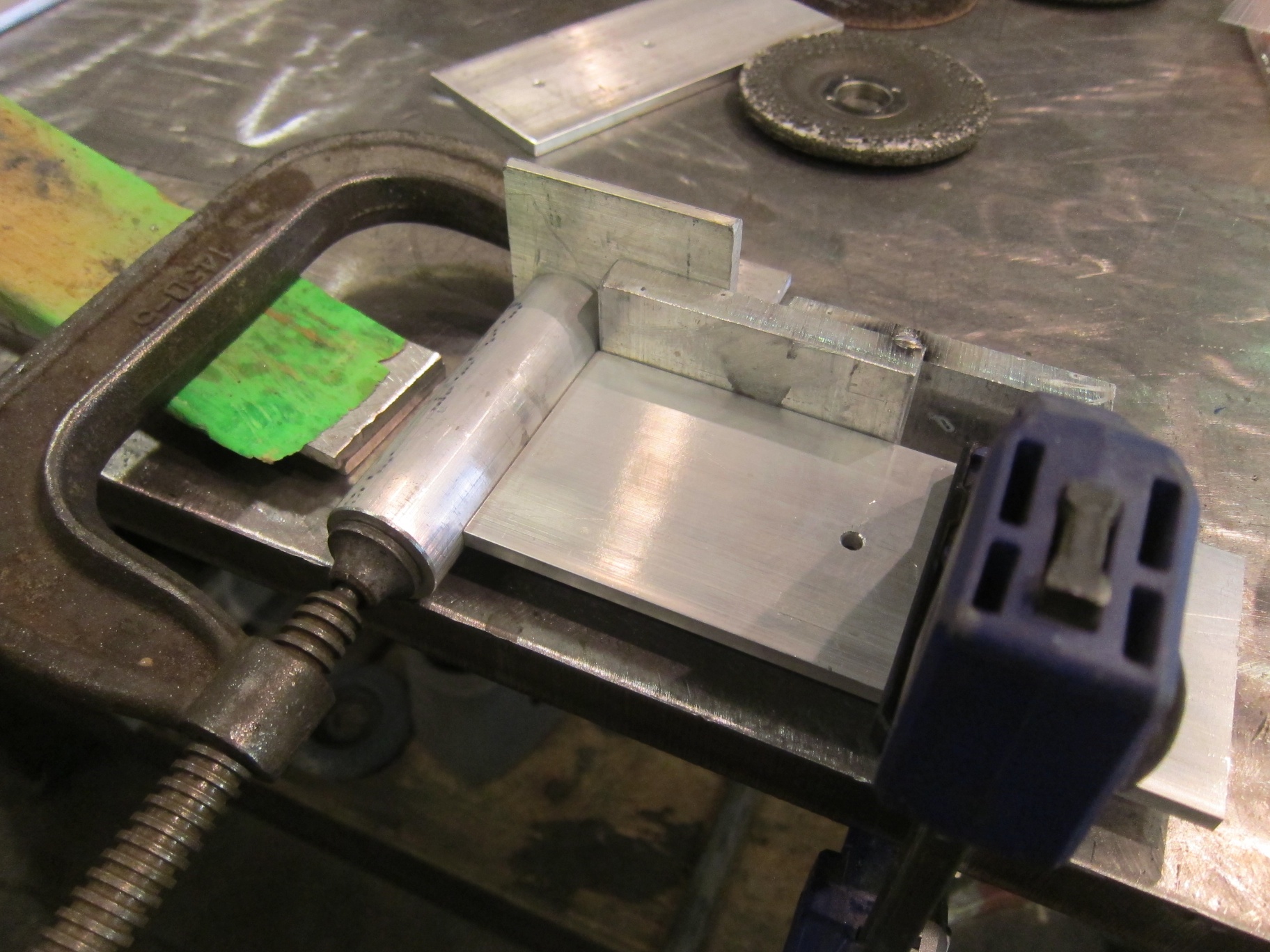
I also used this as an opportunity to to redesign the way the dies are constructed and how they interface with the mold cylinder, but that is for another post! Below are some pictures I took while machining the parts for the cylinder mounts.

photo 1

photo 2 (1)

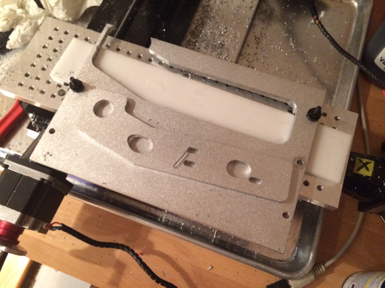
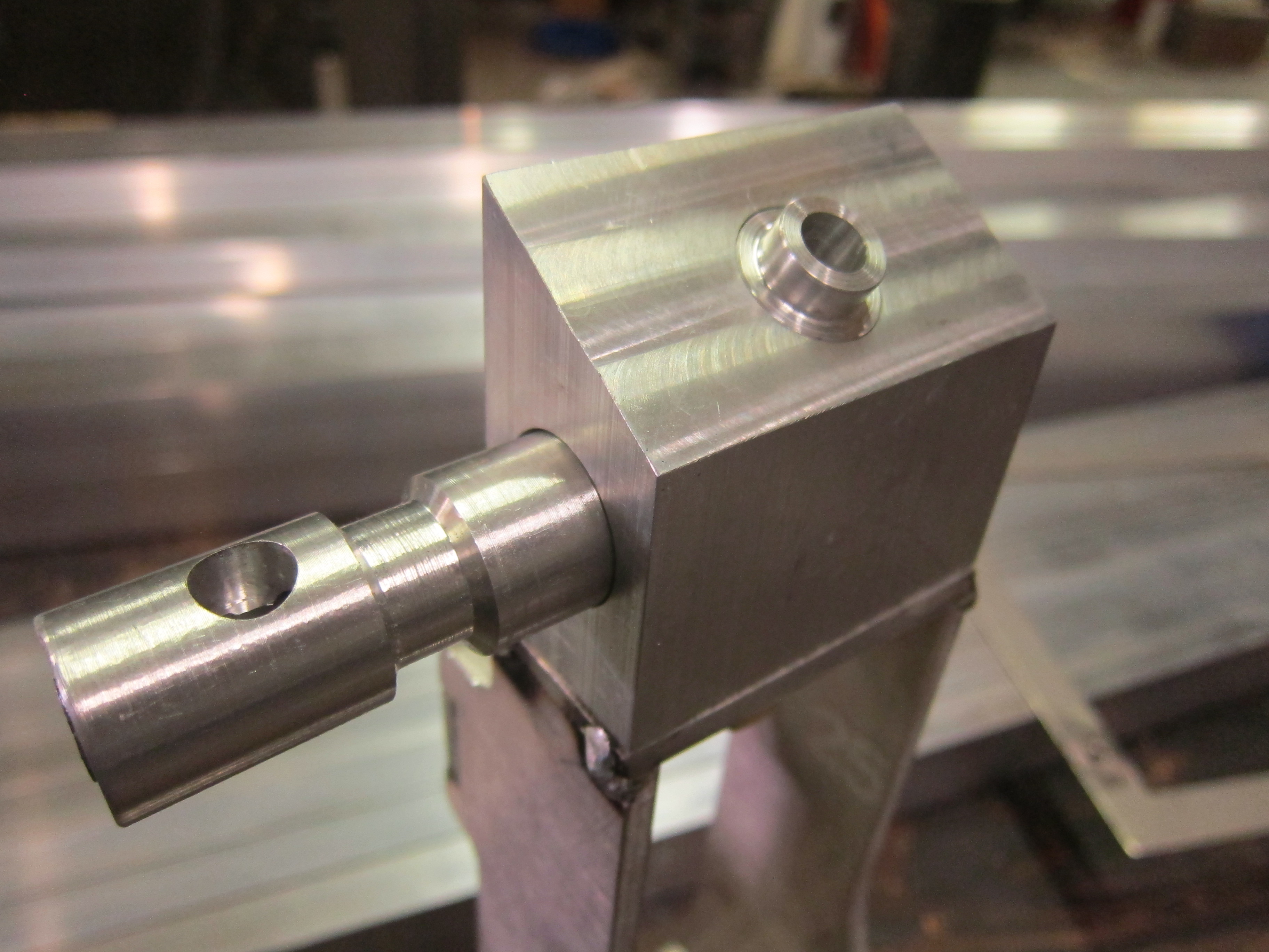
The above part was the first part I CNC cut on my mill and boy was it a learning experience. I probably scrapped 3 or 4 parts before I made the first one correctly. Between fixturing, weird g-code bugs, and getting feeds and speeds right I learned so much on that first part.

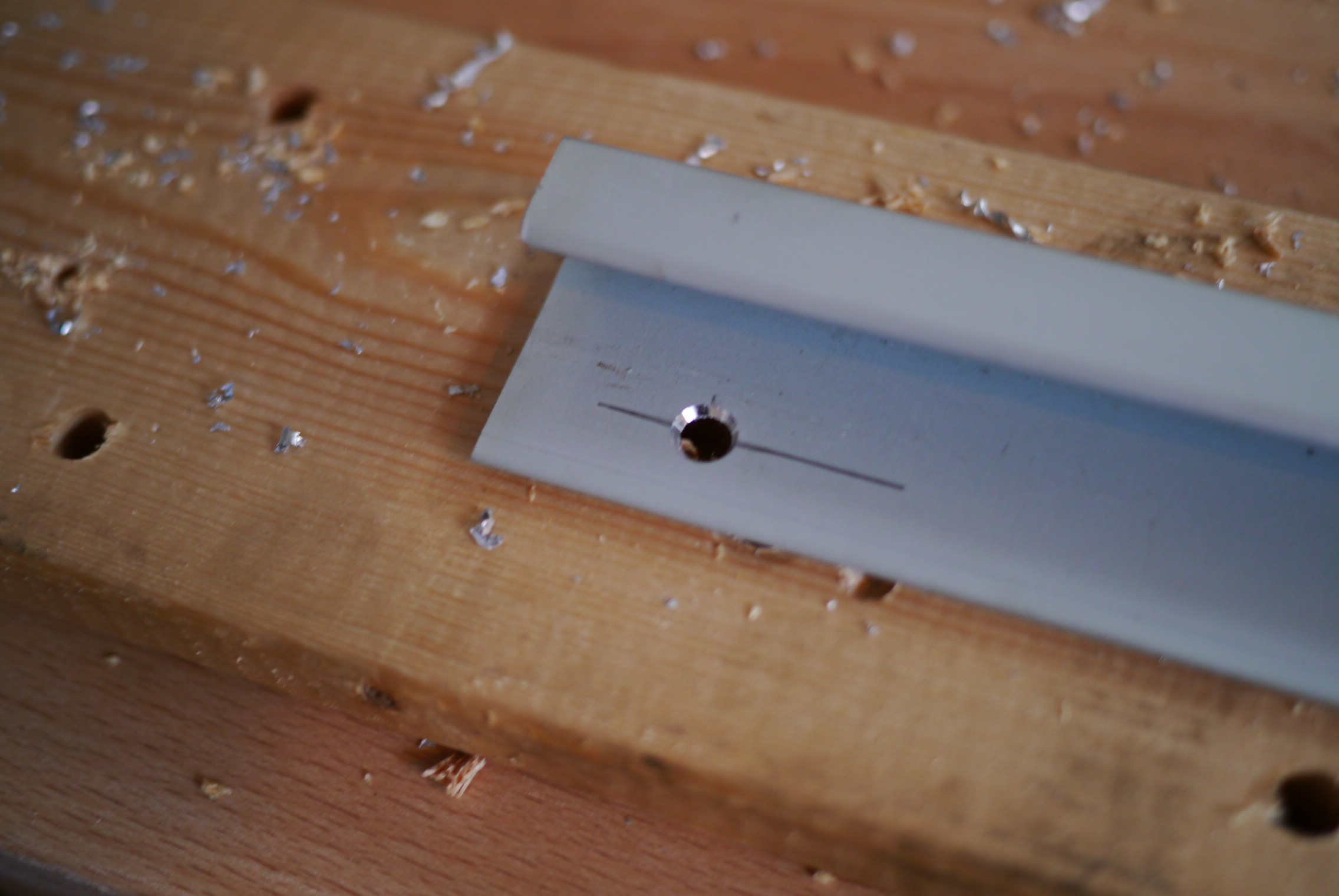
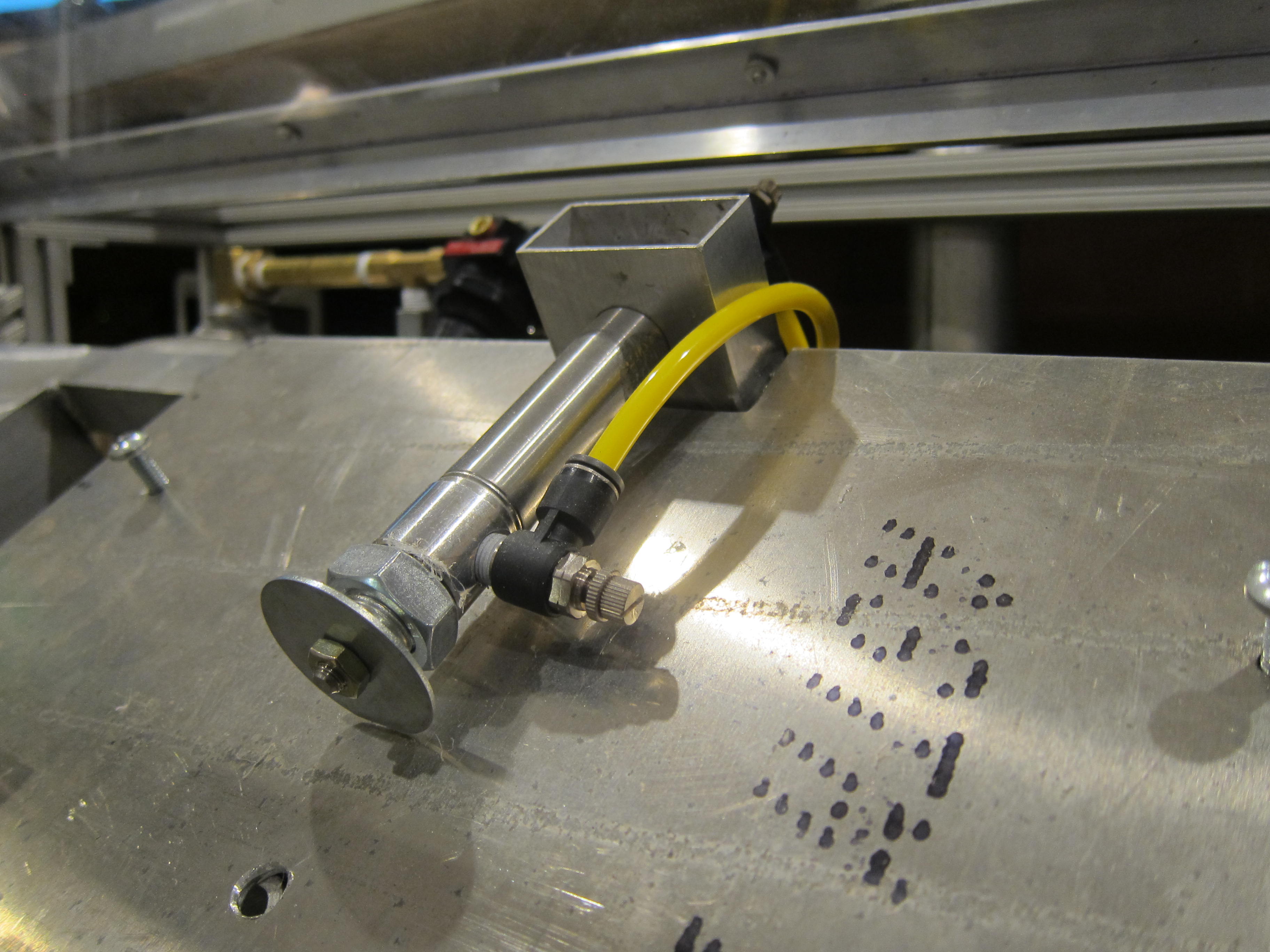
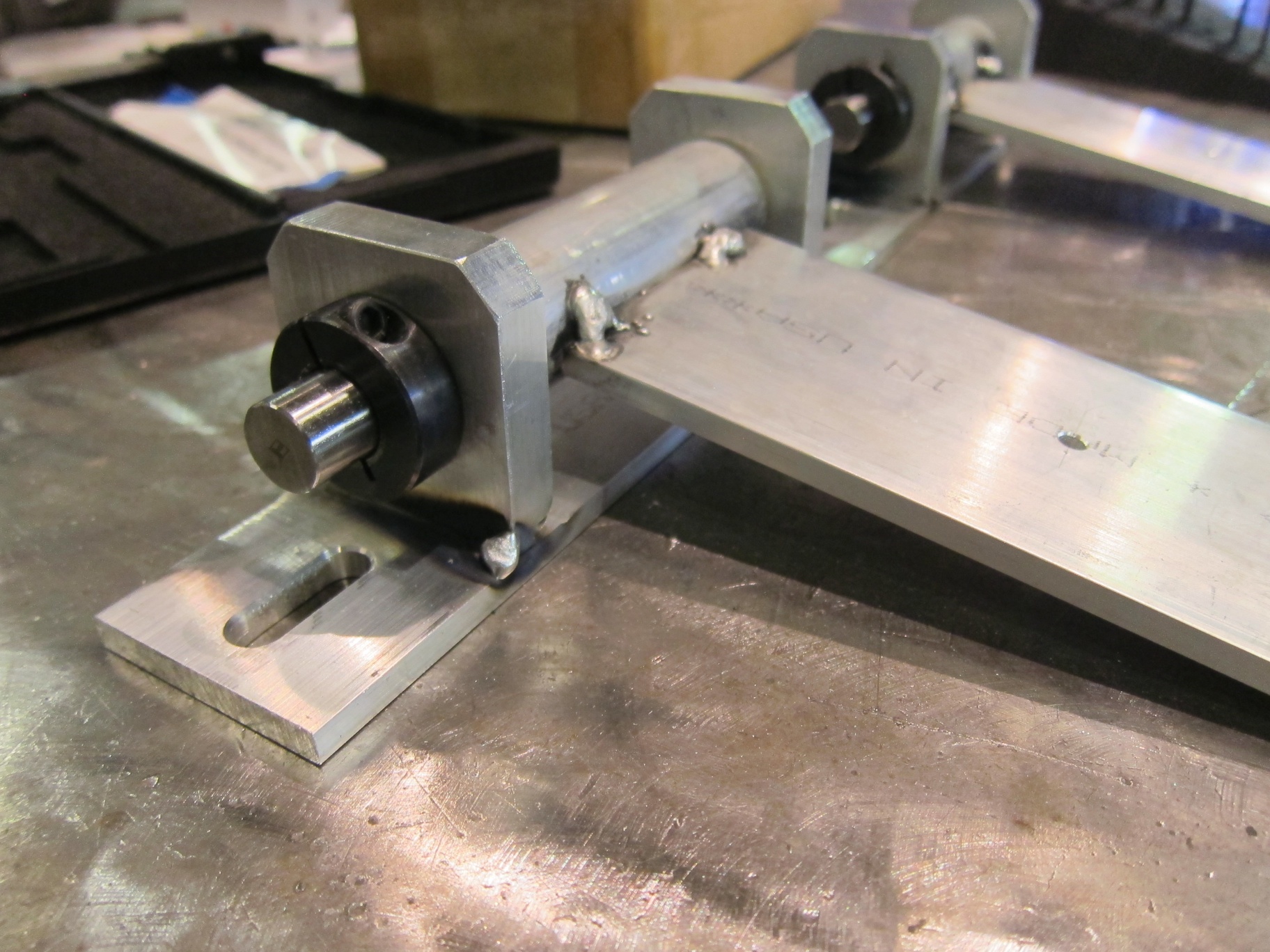
The final product. The slotted screw holes allow me to fine tune the position of the die at the extended position. The bolts holding the bracket to the cylinder have serrations under the heads which bite into the aluminum.  This prevents the cylinder from slipping relative to the bracket when the dies meet. The other large cutouts are clearance holes for the cylinders air fittings.

P1020523


Advertisement

The Apartment Workshop Series: Mini Mill

I’ve been thinking about getting my own mill for several years. I just like the idea of being able to shape metal. For the type of odd ball projects I like, I end up making a lot of my own parts, or customizing off the self ones. Having a mill allows me to do that easier and with much greater precision. I briefly looked at 3D printers, but parts produced on them have such low mechanical strength they really aren’t suited to my projects. Plus I like the idea supporting subtractive manufacturing (milling), as all anyone ever talks about is additive manufacturing (3d printing) these days.

Picking a mill can be a daunting task. There are so many factors to consider: price, working envelope, CNC or manual, construction, spindle type, etc. Being that I planned on operating this inside my living room, my options quickly narrowed. After much research I found several machines that fit the bill:

Little Machine Shop 3900 Solid Column mini mill

480.3900

Taig Micro Mill

nmmill19a

Sherline 2000/5400

5400pic

The taig and sherline are a closer match, as the LMS mill is more of a mini mill, while the others are more micro mills. The LMS mill was my favorite due to the much heavier construction, more powerful motor, and standard r8 spindle. However it is just slightly too large, on it’s own it is not that big, but when you factor in that it will need an enclosure (which is kind of a must have if you plane on running a mill inside your house) it just get’s too big.

Between the taig and sherline, I prefer the taig. It’s heavier steel construction make it much stiffer than the all aluminum sherline. Neither one will handle steel all that well, both can easily do plastic, but for aluminum the extra rigidity of the taig helps reduce chatter.

I was all set to buy a taig, but I came across a deal I could not pass up on craigslist. I got a sherline 2000 CNC ready mill, with steppers for less than 1/3rd the retail price. Whoever was using it last was cutting wood, as there are wood particles all over. It will need to be disassembled cleaned and lubed before use.

photo-2

It fits very nicely on my workbench, and even when an enclosure is added it should not hog too much of the work surface. It did not have a control box, so I’ll need to start looking at stepper drivers, power supplies, and machine control software. Looking forward to this!

The Apartment Workshop Series: Workbench

Due to a job change I no longer have access to the plethora of tools at my old job.  While there are some local hackerspaces, I really like having access to equipment whenever inspiration strikes, rather than having to wait unil the hackerspace is open (also working in your boxers on a Saturday morning). So I am setting up a small workshop in my apartment living room, were I plan to do everything from soldering to machining. This will be the first in a series of articles showing how I setup  and fill this space with various toys.

Every good work shop starts with a good workbench. My money-is-no-object bench would be a Lista cabinet with a maple butcher block top.

18733s3.tifUnfortunately these are disgustingly expensive when bought new and, unless you get lucky on craigslist or an auction, they are still expensive used. My goal is to replicate the Lista bench, but for an order of magnitude cheaper.

One of the first things you should do when designing a workbench is to think hard about what you will actually be using it for. A bench designed for SMT electrical work is a lot different than one for taking engines apart. I plan to use my bench for tool storage, some soldering/electronics, parts storage, machining (once I get a small mill and lathe), light assembly, and taking things apart. I took each of those tasks and figured out what requirements they would impose on my design.t

For tool storage (specifically, hand tools) the Lista cabinets are great as the many thin drawers allow for an enormous amount of storage in a small footprint. Lista cabinets are very similar to rolling tool carts found in garage shops (minus the caster wheels), so that’s where I started looking. I spent several hours researching rolling tool carts on garage journal and reached several conclusions. If you’ve got the money, tool truck boxes (snap on, matco, etc) are hard to beat. They offer the best construction, but at a hefty price tag. Surprisingly, Craftsman tool boxes were generally regarded as the worst quality, people described them as having thin gauge sheet metal, and really bad drawer slides. Also surprisingly, Harbor Freight tool boxes were said to be the best tool box for your money, decent quality, but still affordable.

I ended up getting Harbor Freight item#67831 and selling off the top box to recover some funds. Make sure you get the 26″ model, the brownish 30″ one is much lower quality.

With the tool storage figured out I started looking for a work surface. I like working on wood, as I can sand down and refinish it when it becomes too loaded up with crud (it also looks nice). I went looking for a low cost alternative for the maple top on the Lista bench, and found the Numerar series countertops from Ikea.

It isn’t as deep as I’d like (25″), but the construction (almost 1.5″ thick beech!) and price were spot on. I ended up getting the longer 96″ version, figuring I could always trim it down and use the extra as a lower shelf.

Next up were finding sturdy legs. I considered using wood 4×4 posts, but since this is in my living room and very visible, I wanted it to look a little nicer. I chose speed rail fittings and 1 1/4″ sch 40 aluminum pipe, as they are very strong, but gave it a slightly industrial look. I later found out that McMaster has a nice selection of pre made work bench legs, some with cut outs for electrical outlets.

4885tp1l

For medium sized parts storage I wanted to utilize the area under the work surface by hanging pull out drawers. Since I don’t have access to a cabinet shop to make custom drawers, I came up with my own solution. In my experience work bench drawers usually end up as a disorganized pile of random parts you don’t know what else to do with. Since the drawers are just one large space everything ends up mixing together.

b1a05683-c3be-4c92-b979-dd5af61465e2

My solutions to this was bins with a divider grid system. These bins are dividable down to spaces 1″x1″, allowing for the creation of all sort of odd sides compartments. They also come in a variety of depths and colors, and are stackable.

The drawers slides ended up being one of the harder problems to solve. How do I hang these bins on the under side of the work surface? They have a large lip, and sloped sides so I couldn’t just attach off the self drawer slides. I considered building a self underneath that they could rest on, but interfacing with the speed rail was problematic. I really needed a bracket that the bins could slide on, supported by the lip that runs along the outside. If you know machine tools think of it like box ways. I initially thought about making my own from aluminum square tubing, but that would have been a lot of machining time to cut all the slots and holes (I needed to make about 8-10 slides).

I was browsing McMaster one day and found this aluminum extrusion that is normally used as trim around panels. It has the perfect shape to function as a slide, but still allow me to have a spot to screw it to the underside of the bench.

8427a52p1-j06l

With all the parts acquired I could start putting it all together. I first layer out the hole pattern for the leg fittings, insetting them slightly for appearance.

P1020327

3/16″ clearance hole for a 1/4″ lag bolt.

P1020328

The drawer slides came next, I drilled and counter sunk holes for  #8 wood screws. I had to counter sink them as the drawer would hit any fastener proud of the surface when pulled out.

P1020329

P1020331

P1020332

Aligning and spacing all the slides.

P1020333

P1020337

P1020338

Here’s the almost finished bench. I put on several coats of tung oil to act as a sealer, turning it a golden color. After this was taken I also added an additional leg in the center towards the front, as it needed a little more support mid-span.

P1020346

P1020345

I ended up using the full length of the counter top material since it fit in the space and you can never have enough work surface.

If you’re curious here’s a few shots of the drawers filled with parts.

P1020456 P1020455 P1020451

Sealing it

With the melt tank installed and the pump body assembled, I can now start fitting the injection cylinder to the tank. The large (50mm!) air cylinder moves a piston in the pump body to draw in molten plastic, and then force it into the mold cavity. The piston seals to the pump body with a cup seal. The original mold-a-rama actually has no seal on the piston itself, it seals around the shaft of the injection cylinder, the seal can be seen here:

DSCF5337

This is the injection ram of the mold-a-rama. The seal is in the center of the picture on the aluminum plate, the fiberglass insulation is covering the tank.

Installing the seal was a real bear. The cup seal is sized for a 3″ cylinder, it flares out to ~3.25″ OD to press against the cylinder walls. I needed to compress is to fit it into the cylinder. Softening the seal really had no impact on it’s flexibility, what I really needed was a piston ring compressor. Lacking that I used several daisy chained cable ties. That still didn’t work well so I used some plastic tools to push the seal in.

IMG_0290

I wasn’t sure what to use to insulate the melt tank until a fateful trip to Lowes. In the pipe insulation section I found this self-adhesive aluminum foil backed foam tape. The adhesive holds up to the tank temperatures, and the heat radiating off the tank is noticeable reduced (as measured using the calibrated portion of the back of my hand).

IMG_0292

I looked long and hard for a plastic water tank that was compact, but had a large enough opening to fit the water pump through. The water pump is supposed to be submerged in the water tank, this  will extend the pump life by keeping it cooler. I gave up on finding a plastic tank and made a metal one myself. The body is made from 6″x6″x.120″ wall aluminum tubing with a water jet aluminum flange and lid. A cable gland seals around the power cable. The gold cylinders sticking out from the flange are rivnuts, those along with thumb screws will allow tool-less removal of the water tank  lid for refills. I plan to add a sight glass later on so I can check the water level with out removing the lid.

IMG_0712

The mount for the mold delivery cylinder (the one that pushes the finished plastic part into the retrieval bin) is made from a small piece of 1″x3″ aluminum tubing welded to the top frame and a shaft collar.

IMG_0713

The lower half of the aluminum shaft collar is welded to the back of the rectangular tubing, the upper half is free  and is what clamps onto the cylinder.

IMG_0714

The molder is pretty awkward to move around as it doesn’t sit on a wheeled base. I added handles to each side to make moving it a little easier. The first set of handles I got from McMaster were plastic, thinking the machine couldn’t weight more than 100-150lbs, it turns out I forgot to take into account two very heavy items: the water chiller and the compressor. After putting those in, the machine weights closer to 200lbs. The plastic handles were quickly swapped out for some beefy aluminum ones. I’ll still probably move the machine with the compressor and chiller removed, but now I have a lot move confidence in the handles while moving the machine.

IMG_0717

And finally, before I go, a sneak peak of the new molds!

IMG_0725

Build Blitz Weekend 1

With the deadline for complete rapidly approaching, progress has stepped up. I spent most of my Saturday machining, welding, and cutting.

The bottom of the main valve on top of the injection cylinder has pipe threads to accept a compression fitting. One note about pipe tap, you need to be really careful about your tap depth. If you tap too deep with a tapered pipe tap you can end up in a situation where your fitting bottoms out before the threads tighten up, leaving you with a leaky pipe connection. So pay attention to that thread call out and test with a fitting if you are unsure.

IMG_0261

Here are all the parts for the injector valve assembly. This regulates the flow of plastic and air into the mold cavity via the shuttle valve sliding back and forth.

IMG_0262

Starting hole layout for the melt tank. I kind of wish I had used steel for the tank instead of stainless steel. Stainless is a real pain to work with. It’s hard to cut, hard to drill, hard to bend, hard to weld. Just really unfriendly in general. The original mold-a-ramas used an aluminum tank, but I got a really good deal on the stainless tank I started with to make this part.

IMG_0263

Another area where I’m differing from the original mold-a-ramas is the piston design. The original injection cylinder sealed agains the rod of the hydraulic cylinder used to inject plastic for the melt tank to the mold. In my design I have the seal on the piston. I’m very nervous excited to see how well this works. There is another disk, not shown, that will retain the seal against this piston.

IMG_0264 IMG_0265 IMG_0266


A few more from this weekend:

IMG_0267

I really need to hire a hand model.

IMG_0268


There are a few more bits and pieces that need to be fabricated (frame for cover, water tank, brackets for a few items), but the bulk of it is done. Next up is programming, wiring, and test/debug.

Mold Machine, Meet Welder

Metal met welder this week in the shop. I finished machining a few brackets and started tack welding some assemblies together.

Welding aluminum is tricky, the coefficient of thermal expansion is almost twice that of steel, which means it moves from the heat of the weld, much more so than steel. Here’s some tips when welding together plates of aluminum:

1. Aluminum moves during welding. A lot. Start slowly and clamp together anything that may warp or shift during welding.

m8 034

2. Check for square and check your dimensions, early and often. Since the material moves so much during welding, what started out nice and square will end up looking like a pretzel. So weld slowly and move around, alternately tacking on opposites sides (the heat from the weld has a tendency to pull the plates together on the welded side and apart on the opposite side. Recheck for square/level after very few tacks.

m8 035

3. I always find faces in the stuff I work on:

m8 036

I was able to tack together the complete injection cylinder, minus a small plate on top which I later added to give me a spot to bolt the valve block to.

m8 039

I also tacked together the swinging mold cylinder brackets:

m8 033 (1)

Having the mold cylinders swing up allows me to service the parts inside the melt tank without disturbing the alignment of the molds.

m8 038

m8 037

And the sub-frame that a majority of the machine gets attached to.

photo (13)

That’s it for now. Next up is cutting the 1×1 angle for the top cover and finishing some parts on the mill and lathe.