
Wow somehow I forgot to post a video I had made of the Mini Molder running a cycle. Oops.
Mini Molder
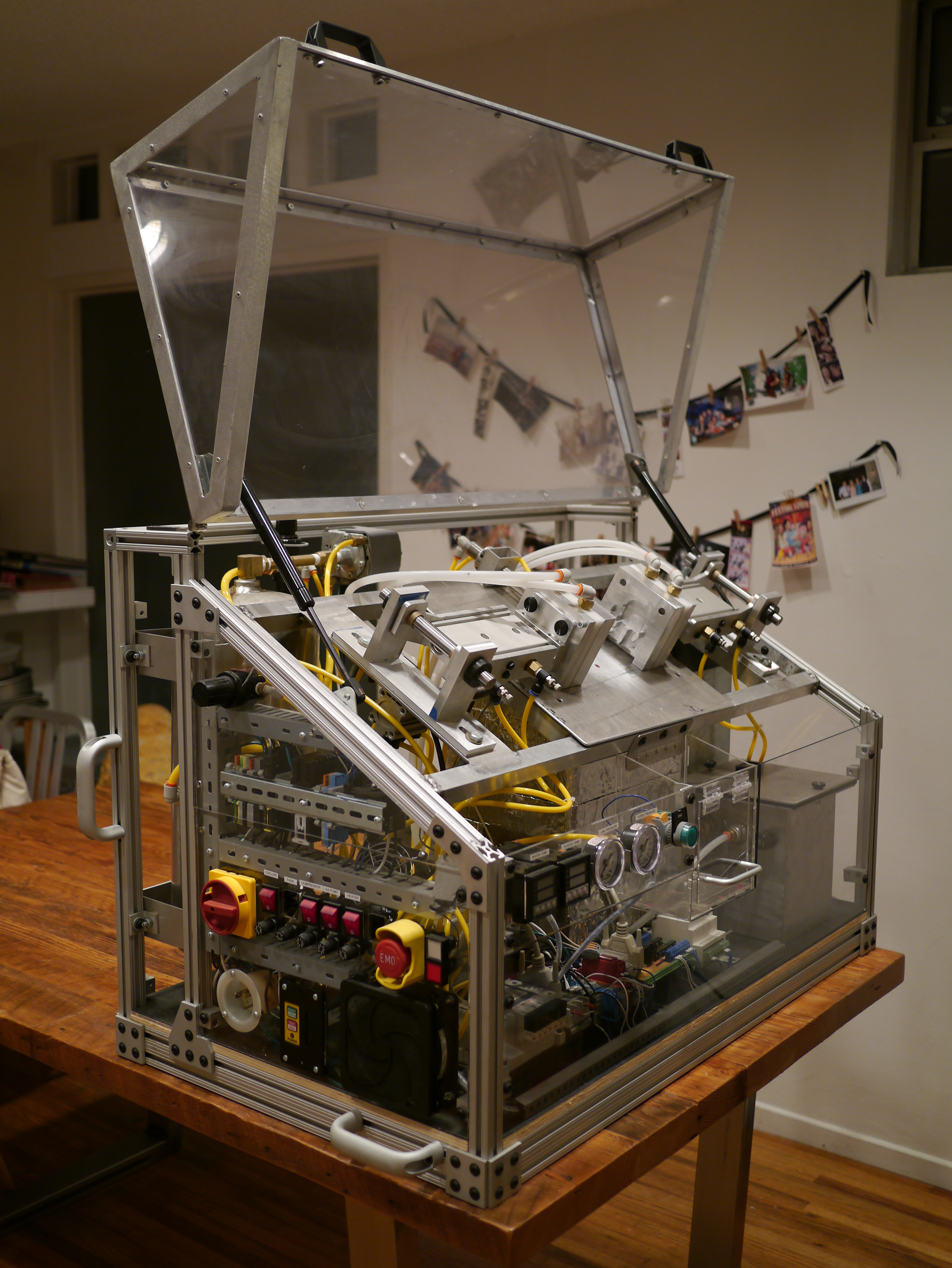
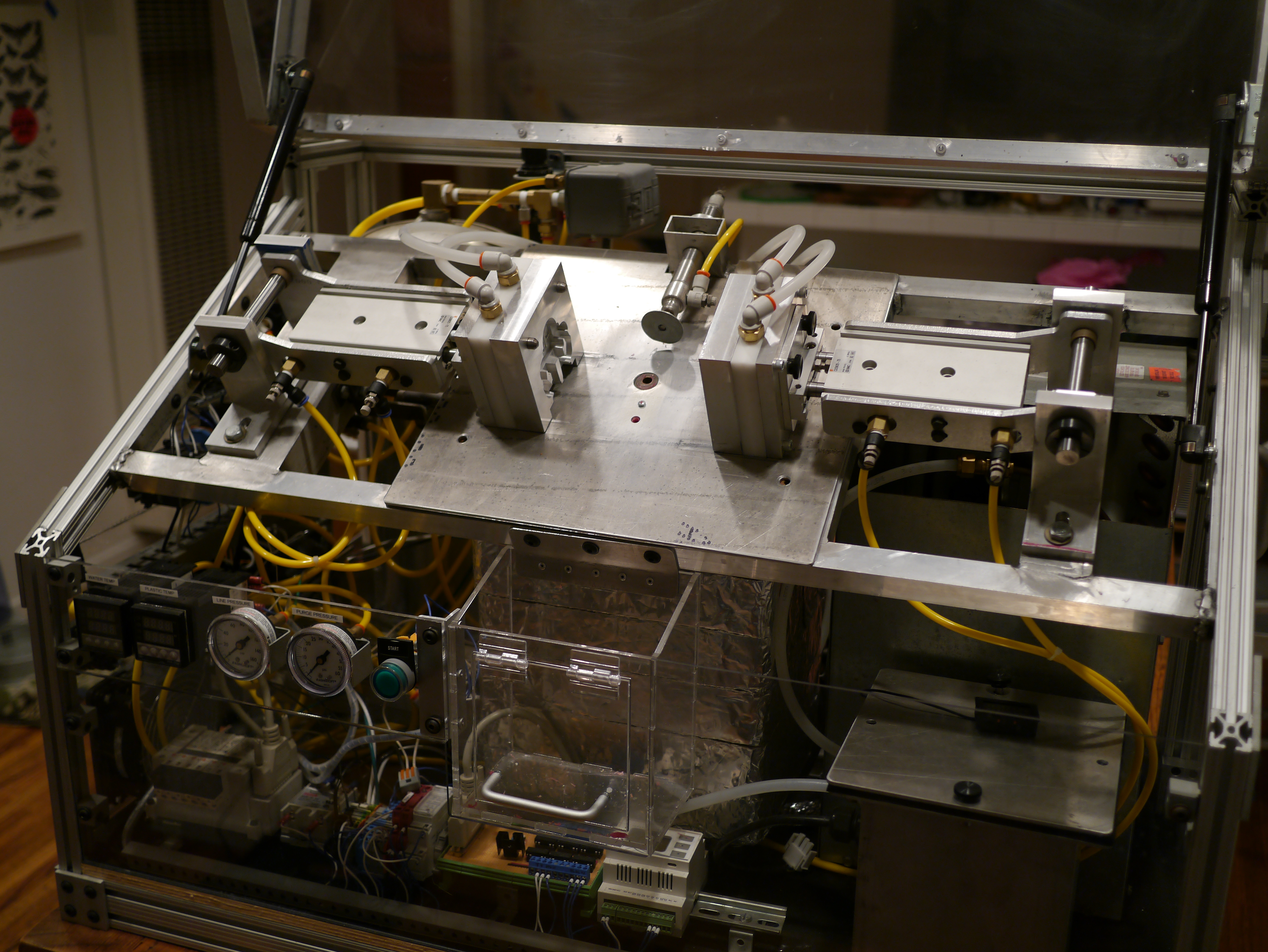
Mini Molder Finished Photos!
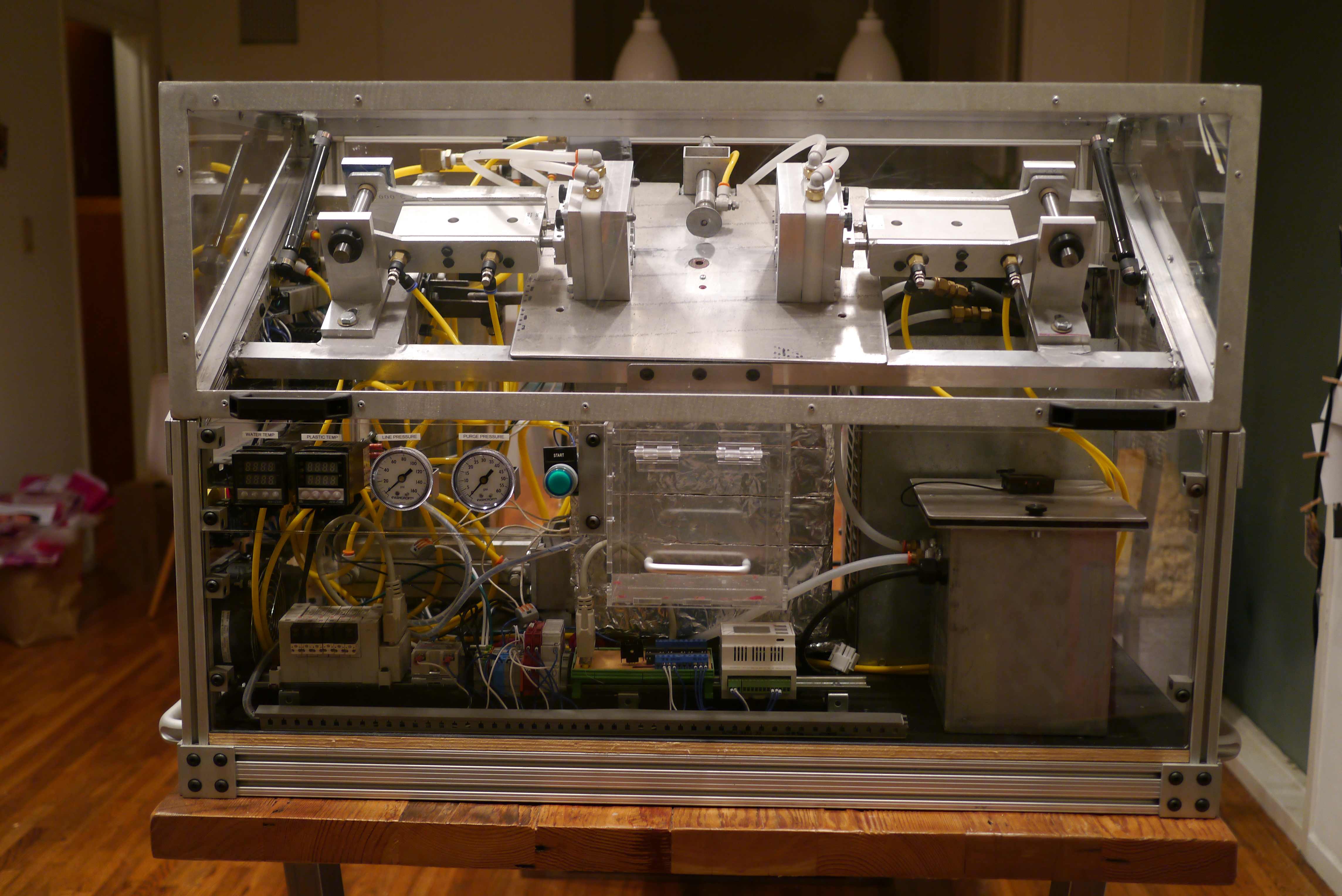
It just occurred to me that I never put up photos of the finished Mini Molder. Here they are!
Also, if you’re wondering what’s next for the molder, wonder no more. Over the next year I plan to upgrade the machine with an automatic pellet feeder. One of the things that kept me from running the molder non-stop at Maker Faire last year was having to open the melt pot and pour in more PE wax pellets. This dropped the tank temperutre drastically and stopped the machine for a solid 45min while it got back up to temperaute .The pellet feeder will put in a little at a time, keeping the melt pot hot.


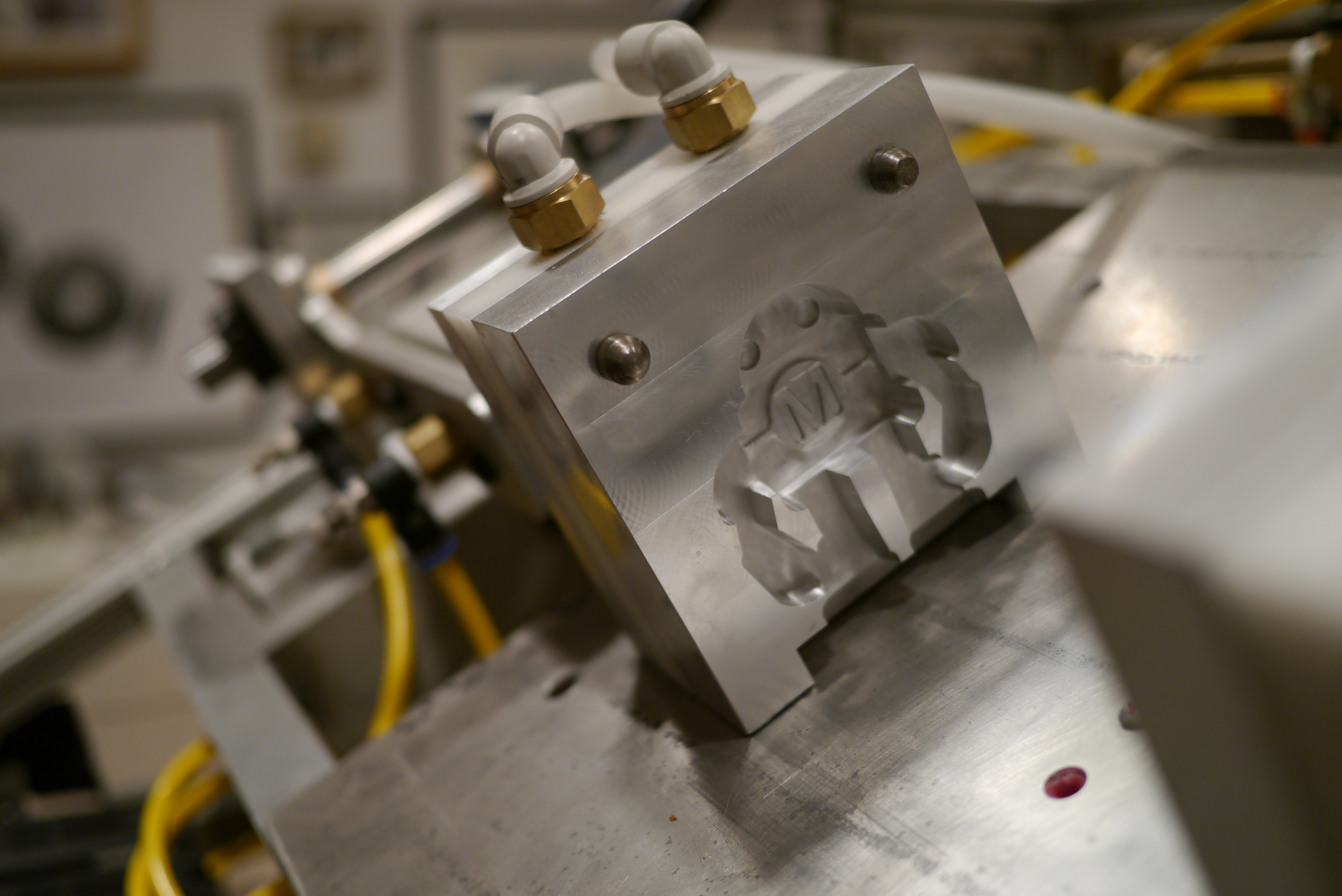
Custom Dies for the Mini Molder
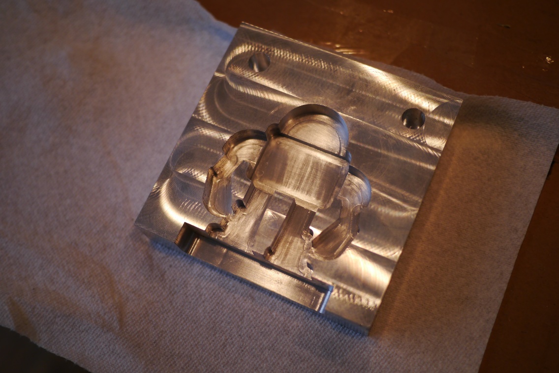
Since I decided to debut the mini molder at Maker Faire bay area a custom mold was in order. One of the more iconic images for Maker Faire is the Makey robot figure. It has roughly the correct proportions for a mold-a-rama figure, and a simple enough profile for my basic CNC abilities. I found an image of a pin sold in the maker shed.

I traced the above image in solidworks and created a model of the figure.

The base on the bottom is partly for stability, but also a result of the liquid plastic entry and exit ports. Those ports are not quiet aligned with the legs of the robot, so the flat base ensures the mold cavity is always around the two liquid plastic ports.
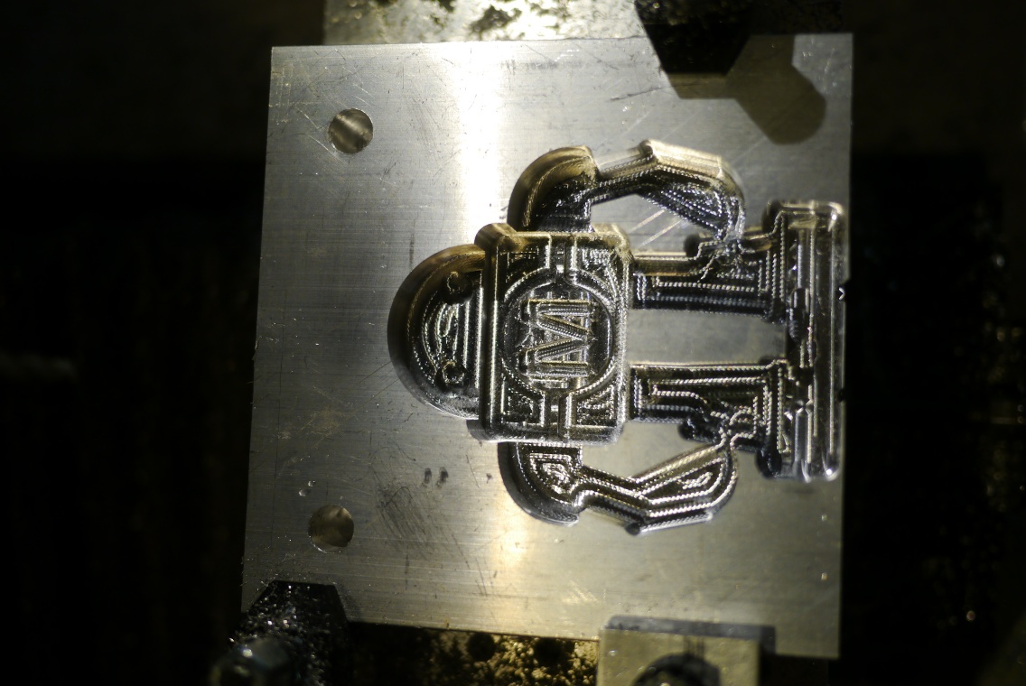
Once the figure was modeled I created mold halves using the cavity feature in solidworks and added various holes for screws.

In most injection molding dies, water channels are used to route chilled water around the mold, this helps cool the part faster enabling a faster cycle time. Mold-a-rama dies had a water jacket cast into the back side of every mold die. The mold cylinder mounting plate on the back doubled as a block off for the water jacket.
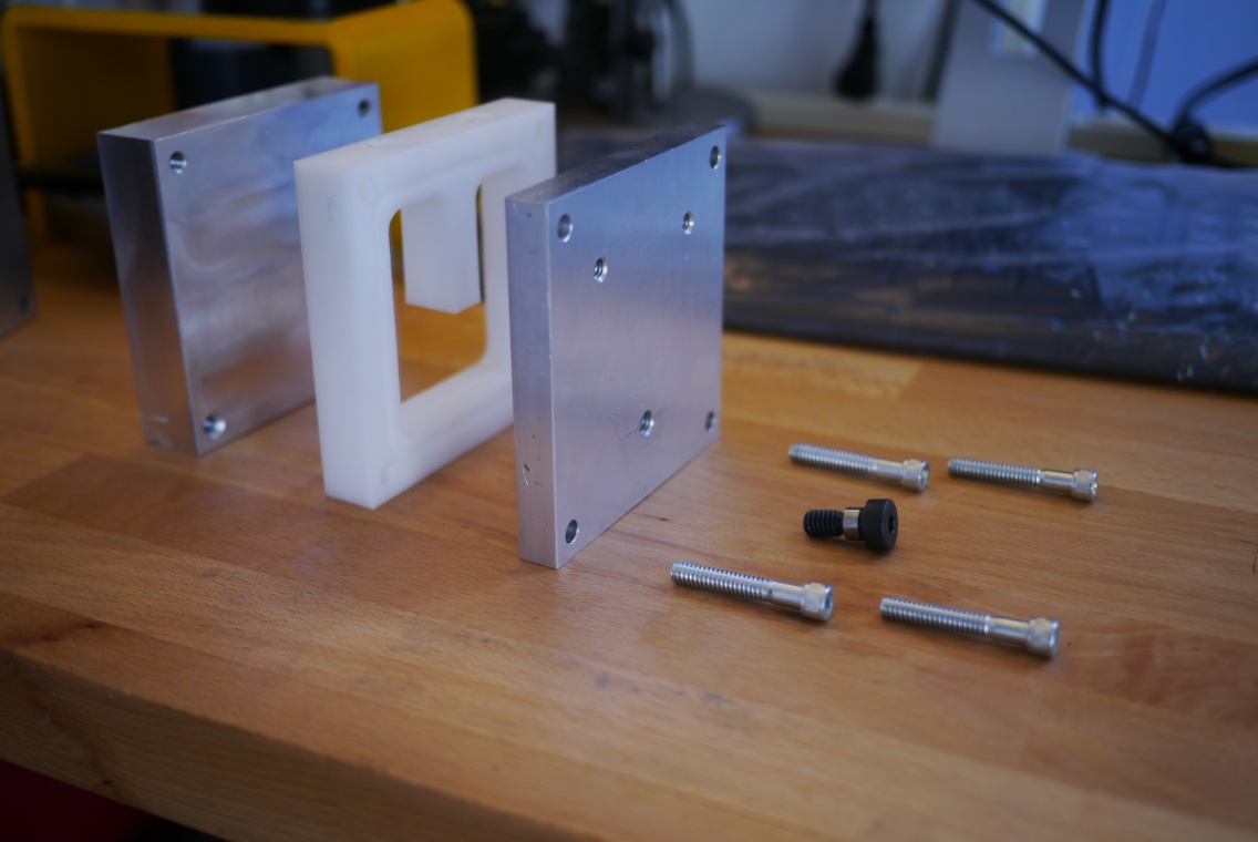
The mold dies I designed consist of several parts:
- Mold face with part cavity
- Water channel spacer plate
- Rear mount plate
I decided to make the mold die in multiple parts for a few reason. The first is that more of the mold is reusable should I want to make a new mold design. If I had cut the channel for the water directly in the back of the mold, I would have to cut that same feature in the back of every new mold as well. Making a separate water channel spacer means fewer setups on the CNC mill. The second is that cutting a water jacket in the back of an aluminum mold would take an enormous amount of time on my little CNC mill, the much faster material removal rate of delrin made this an easy decision.
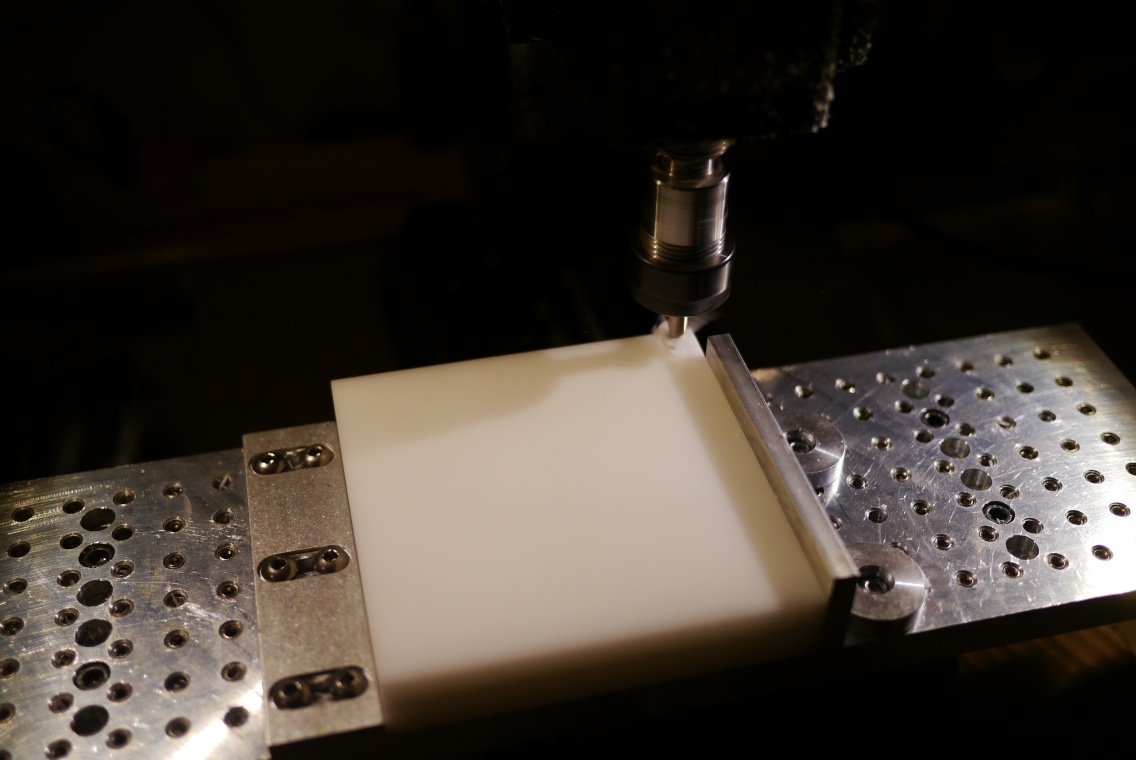
What follows is a mostly complete step-by-step of the machining process for the mold spacers.
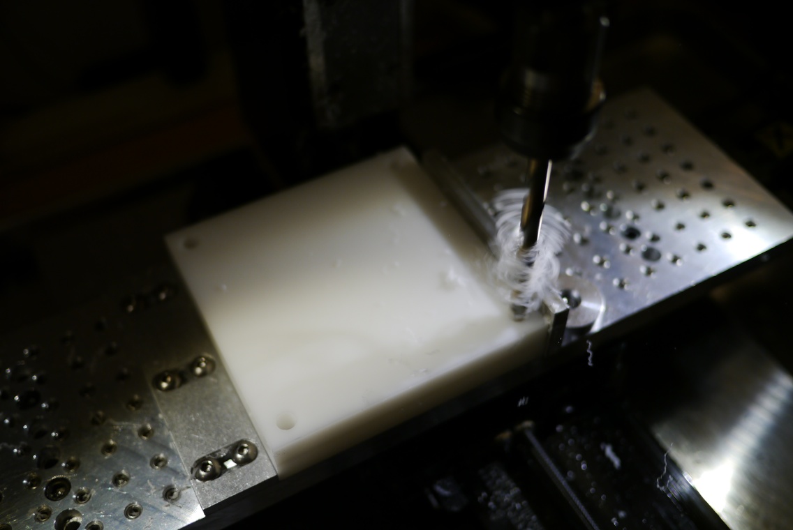
After rough cutting the delrin stock and squaring the sides, it is tightened down to the tool plate in my mill.

Setting the tool height so my mill knows where the top of the stock is relative to the tip of the cutter (center drill in this case)

Drilling clearance holes for the 1/4-20 screws that hold all the mold sandwich together.
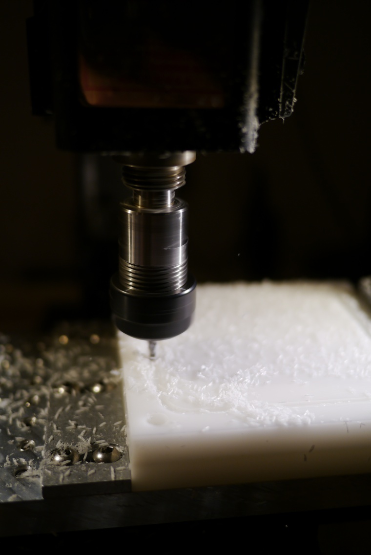
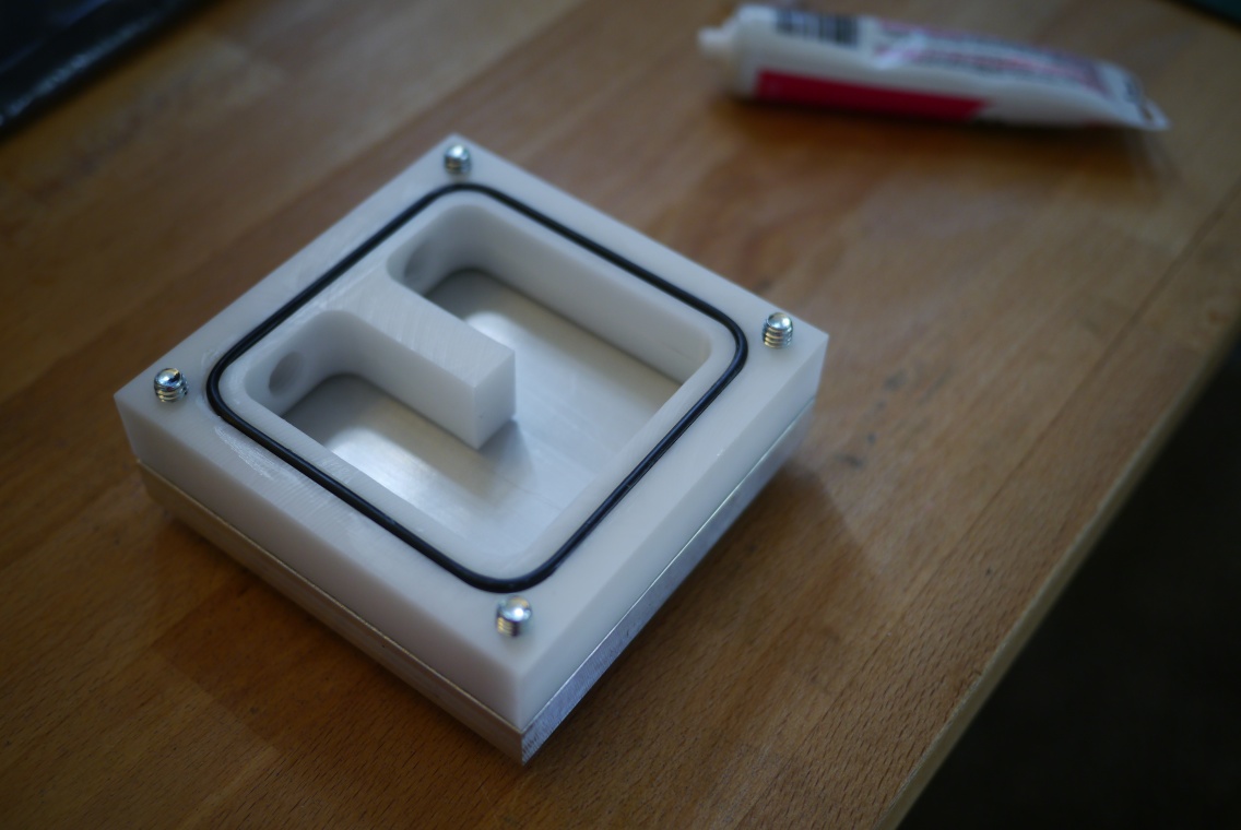
1/8″ 2 flute carbide end mill creating the o-ring groove.
This center u-shaped section is where the water flows into and out of the mold cooling cavity. The entire center section needs to be cut out. Since I don’t want to cut into my tool plate, I cut the slot to half-depth, then flipped the part over and cut it again. Flipping parts is always tricky, as any small misalignment will show up were the two cuts meet.
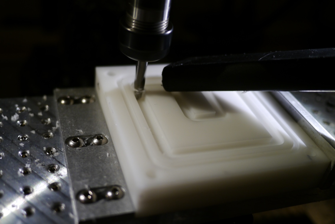
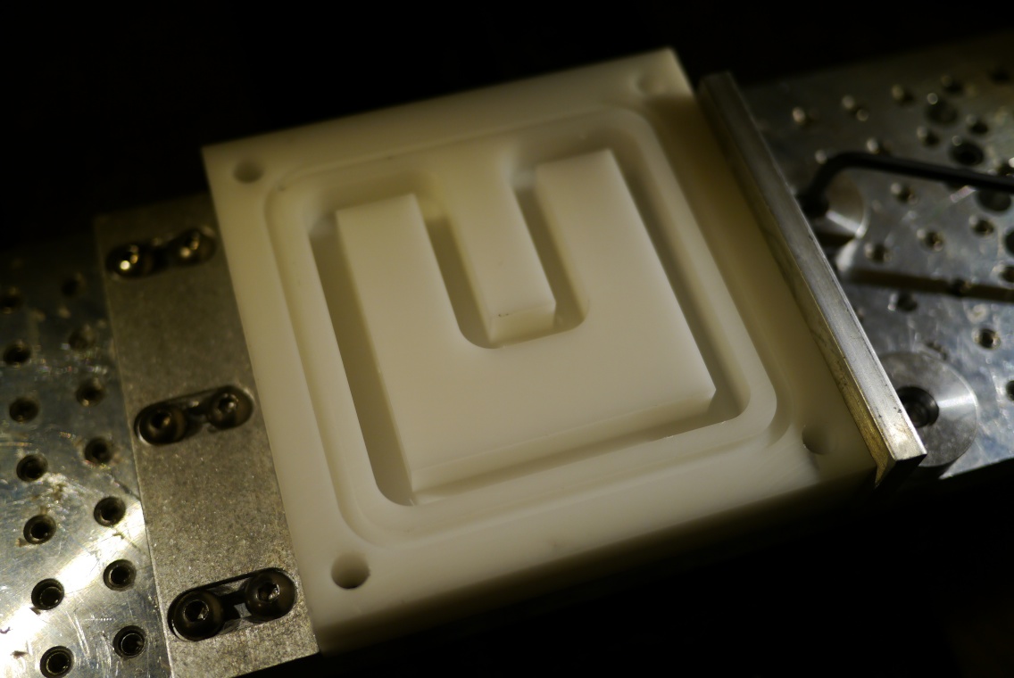
In the first part I made, I removed all the material bit by bit (machinists call this pocketing), this took a long time. In the second part I used a 1/4″ 2 flute carbide end mill to cut a half depth slot around the piece of delrin that was to be removed. Flipping the part over, re-cutting the same path and the whole center section comes out in one piece.
The last step on the spacer plate is to drill and tap the NPT threads for the pipe fittings. The drill bit needed to drill this hole was too long to fit in my mill, with its limited z-travel. So I milled out the hole using a 3/16″ end mill.


Taping large threads like 3/8 NPT take a decent amount of torque, so your part should be firmly mounted. I sandwiched the spacer plate between two backer plates, put them in my screwless vise, and then clamped the vise to my shop table.

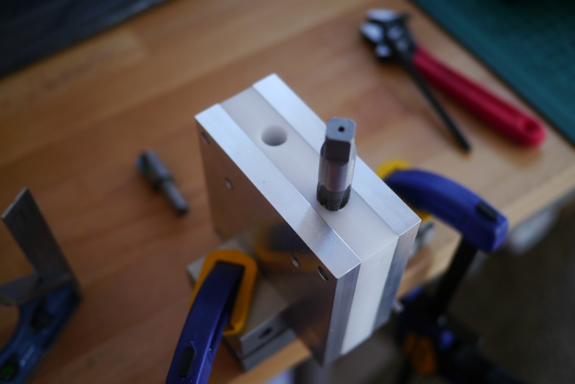
Getting a straight start on your tap can be pretty tough without a tap guide, or performing the operation in a mill. I used a small square to align the tap, going slowly and re-checking after each turn.

The mold faces started life as a piece of 4″x1″x12″ 6061 aluminum. Like the spacer plate before, they were cut to rough size on a band saw and then squared up with a fly cutter on my sherline mill. I don’t have as many pictures of the milling process, but I did take a time lapse video.


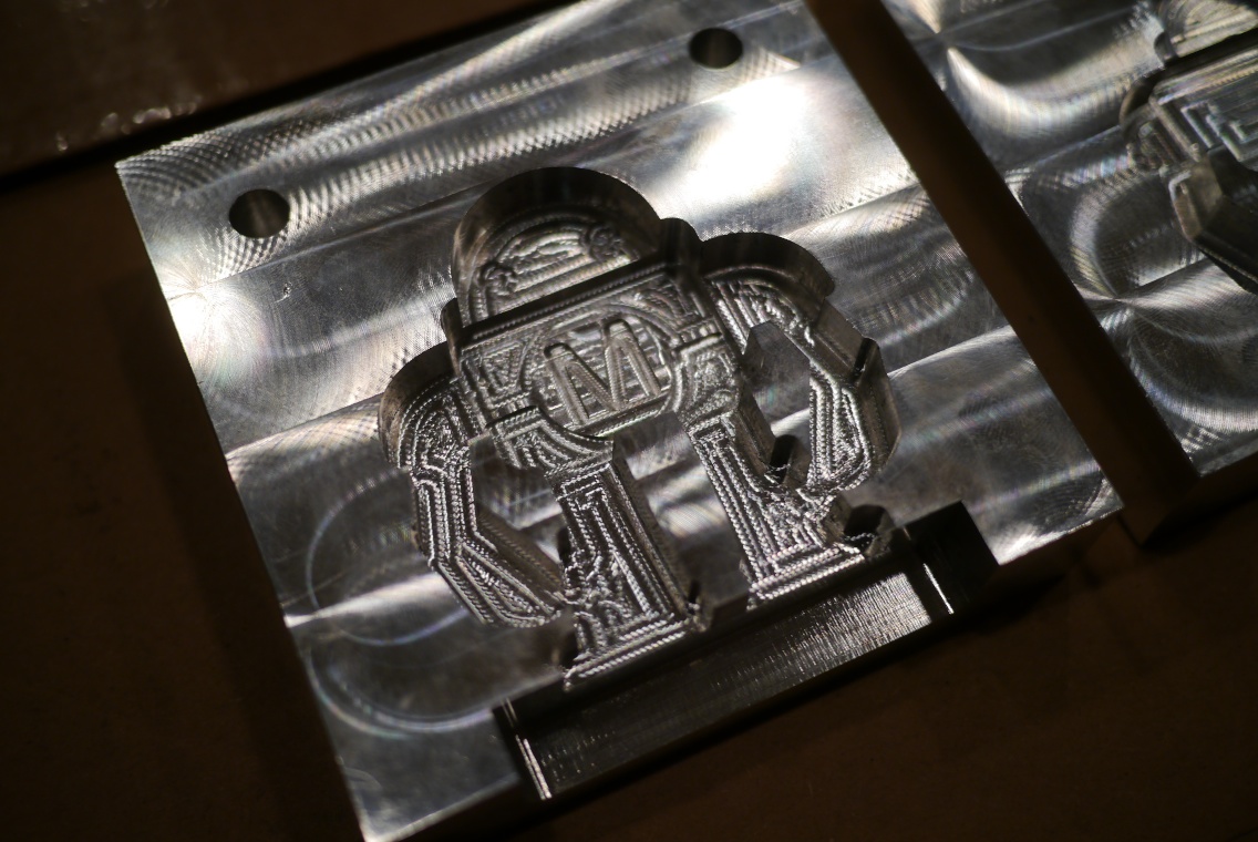
To remove the tooling marks left by the mill cutters, I used 400 grit wet or dry sand paper and some free labor (thanks Ashley!) It was time-consuming, but gave me a greater appreciation for what goes into achieving a mirror like finish on all the plastic products I see.
Exploded view of one of the mold dies (minus o-rings).
Spacer with its two o-rings. I used plumbers faucet grease as an o-ring lubricant as it was what I had on hand.

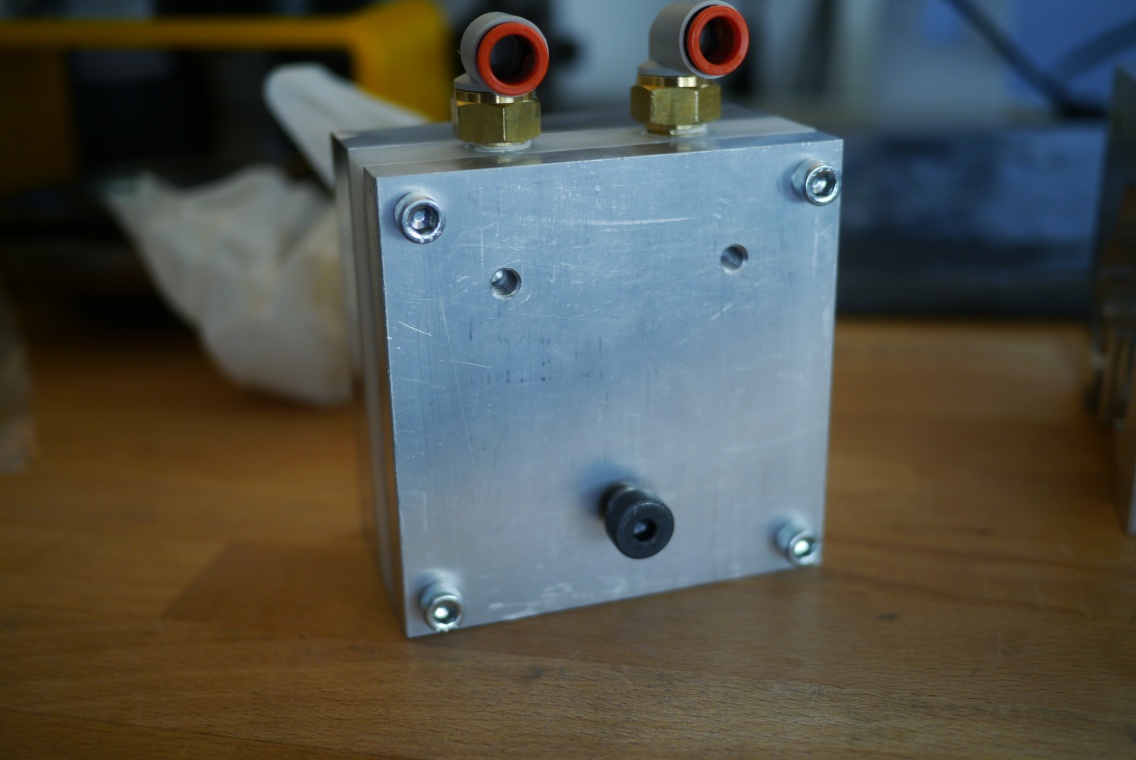
Assembled with pipe fittings installed.

A Pump, a Check Valve, a Problem
During testing I noticed the molder’s plastic injection pump stopped working after 2-3 consecutive pumps. If the molder sat for a few hours it would work for a few shots, but shoot blanks soon after. The path from plastic melt tank to mold goes like this:
1. The injection cylinder retracts, creating a vacuum in the pump body, which draws plastic through a check valve and into the pump body.
2. With the pump body full of molten plastic, the injection cylinder extends, building pressure inside the pump, closing the check valve and forcing the plastic through the pump outlet
3. Hot plastic travels through a copper tube to the shuttle valve, if the shuttle valve is in the plastic injection position, the plastic pass through the valve and up to the opening in the bottom of the mold.
I checked that the shuttle valve in the pump body was switching and that the injection cylinder was extending fully, both were operating correctly. The next place I could see a problem occurring was at the pump inlet and check valve.
Getting to the check valve means removing the pump body, which means draining the tank. I put a drain port on the tank, but the close proximity to the base make draining a bit of a task. A make shift funnel made from aluminum foil did the trick.

After removing the pump body from the molder I inspected the check valve and found a few particles, burnt plastic and bits of cork insulation, but nothing that would clog the inlet completely.
While I had the check valve out, I inspected the flow path through the valve. The path consisted of some very small holes (~0.050″), the molten plastic having the constancy of honey, this particular check valve could not possibly have flowed enough to recharge the pump when the piston retracted. It’s clear I didn’t consider the viscosity of the working fluid when choosing the check valve.
I looked for a check valve with the largest flow path that would fit on the 3/8″ NPT pump inlet. That happened to be a swing style check valve. The new check valve is much larger than the old one, so much so that it won’t fit in the same spot, coming directly out of the pump. A 90 degree fitting in between the pump body and the check valve put it in the upright position.
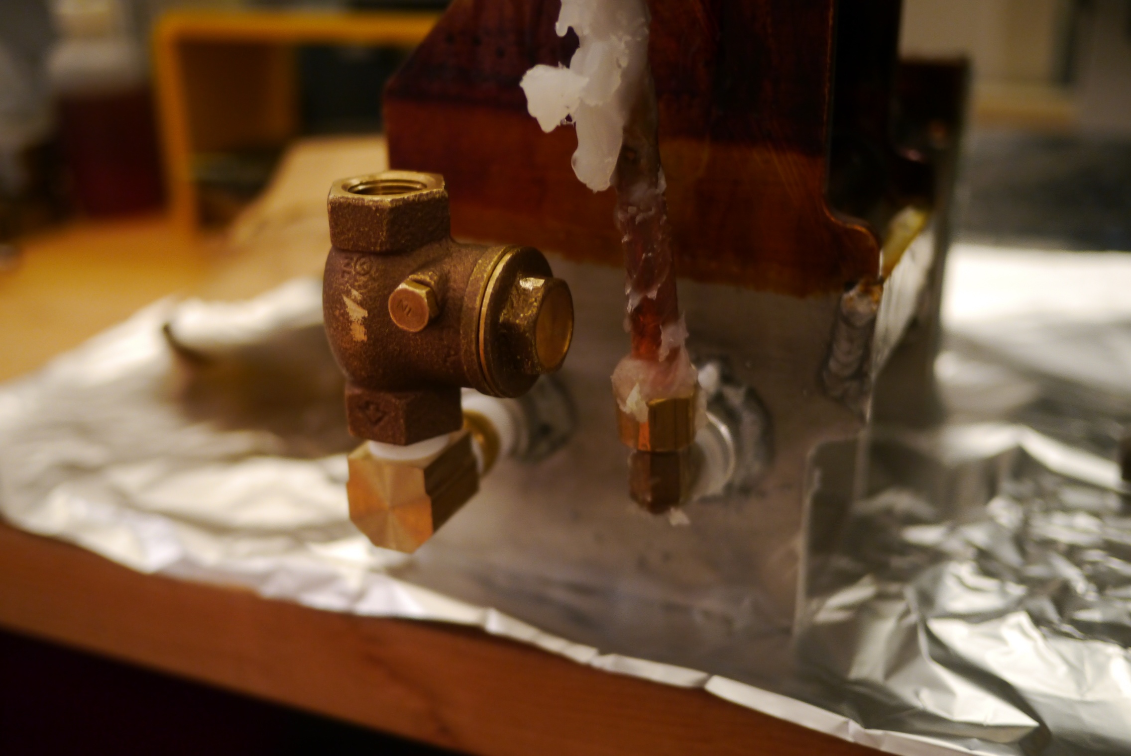
While I had the pump out, I took this opportunity to fix the threads in the pumps outlet port.

They had become cross threaded with the fitting that was installed, and was leaking when the pump pressure built up. A few turns of a 3/8 NPT tap and the threads were cleaned up.
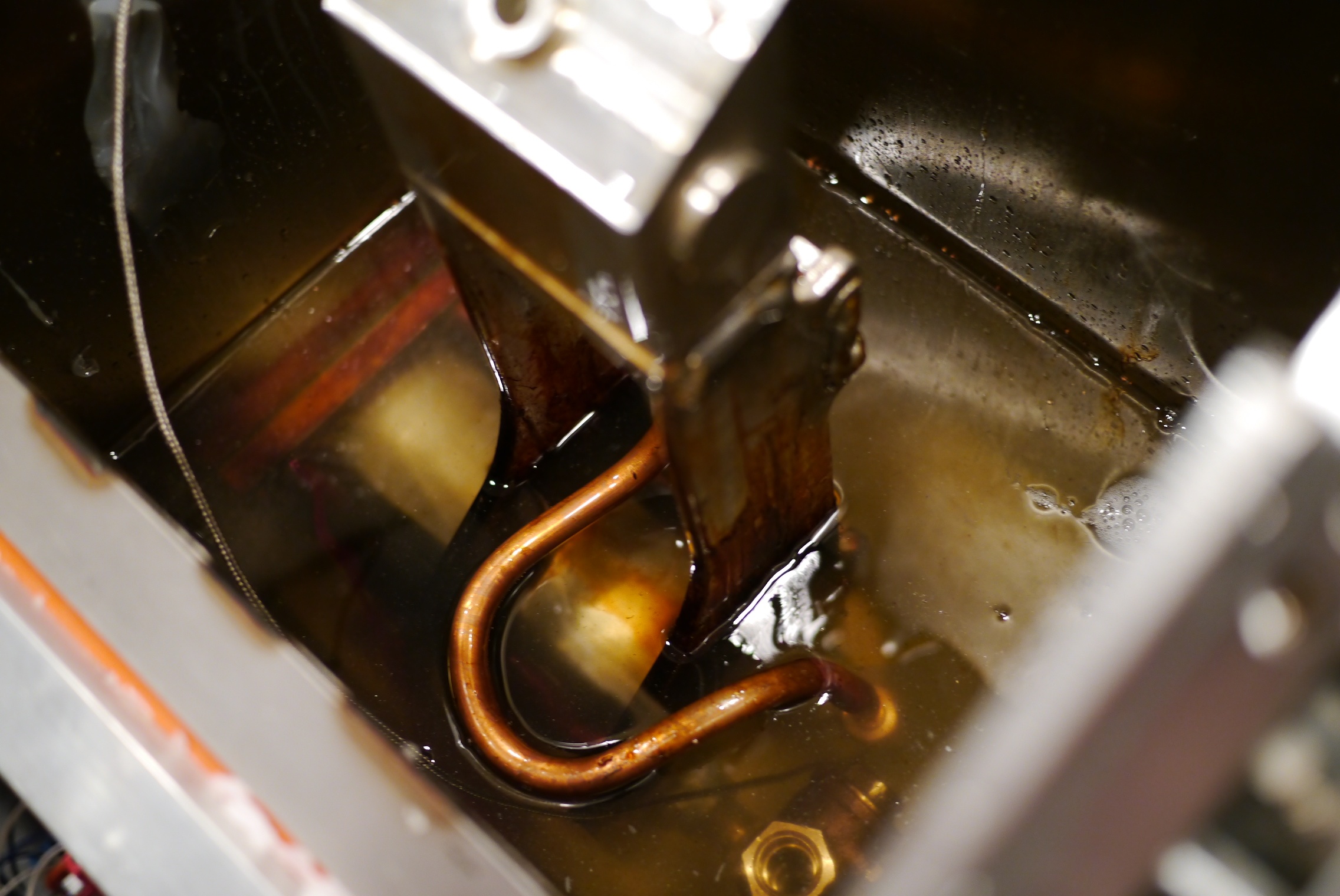
Fast forward a few hours and the pump is installed and has a tank of liquid PE wax around it. Cycling the pump’s pneumatic cylinder it was clear the new valve was a huge improvement. You could see a steady stream of plastic flow into the check valve every time the cylinder retracted. Cycling the injection cylinder back and forth yielded a consistent flow from the shuttle valve outlet.
Over Center, Under Pressure
One of the ways the mold-a-rama process differs from traditional injection molding is the way the part is ejected from the mold. Usually one of the dies has a set of ejector pins that pop the part out of the mold (if you look at most plastic products you will see a series of small circular or square indentations on the back side, these are small marks left from when the ejector pin pressed the part out of the mold.) In this lego manufacturing video you can see the thin ejector pins stick out right as the part falls out of the mold at the 40sec mark.
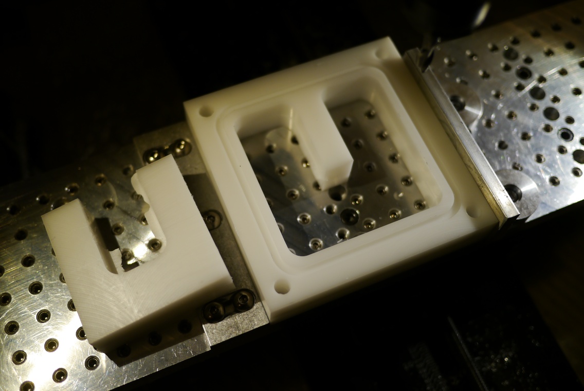
To keep the machine simple, the mold-a-rama uses no ejector pins. Instead it relies on the part staying in place while the molds open around it. This is possible because the bottom of mold-a-rama die is actually open. This is a picture of the bottom of my mold dies.

The base of the plastic part sticks to the tank lid (which is why all mold-a-rama toys have some kind of flat base.) Traditional injection molding dies form a sealed cavity when they meet, save for the sprue, the opening where plastic enters the mold. Mold-a-rama dies form a complete cavity by sealing against the melt tank lid (the aluminum square below the molds, which also serves as a cover for the plastic melting tank). As you can imagine, it is very important that the dies press firmly against the melt tank lid, otherwise plastic would leak out between the dies and the tank lid.
Below is a CAD screenshot of the mold cylinder assembly I originally made, the die is the blue rectangle. Can you guess if they functioned correctly?
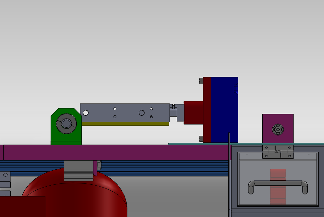
The answer is no, no they did not. When the dies closed against each other they popped up slightly, instead of being forced downward to seal against the melt tank. The can been seen in the video below. Watch towards the end and you will see the pair of molds raise up slightly.
If I were to run this in an injection cycle I would have melted plastic spewing out. After some head scratching I realized I had the mold cylinders (the grey rectangular part in the CAD screen shot) placed above the pivot point (the grey circular part), this meant that when the molds pressed against each other it tended to rotate the entire mold cylinder and mold counter clockwise about the pivot point, which meant the mold moved in the upwards direction. I tested this theory by flipping the entire mold cylinder and mount upside down. Now the mold cylinder was below the pivot point, which meant the mold cylinder now tended to rotate clockwise about the pivot point, forcing the die downward. This video shows how the molds are forced downward when they meet.
Armed with this realization, I redesigned the mold cylinder mounts to match the flipped version I had tested. With the two designs side by side (old on left, new on right) you can see how the mold cylinder location has changed relative to the pivot point.

I also used this as an opportunity to to redesign the way the dies are constructed and how they interface with the mold cylinder, but that is for another post! Below are some pictures I took while machining the parts for the cylinder mounts.
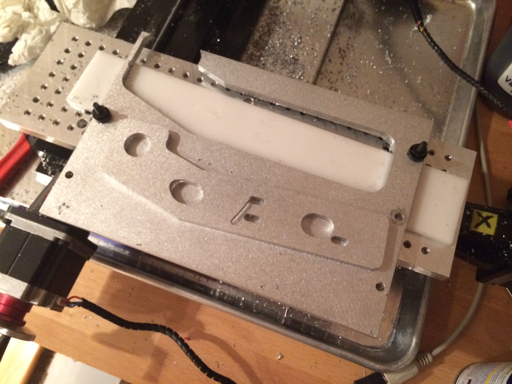
The above part was the first part I CNC cut on my mill and boy was it a learning experience. I probably scrapped 3 or 4 parts before I made the first one correctly. Between fixturing, weird g-code bugs, and getting feeds and speeds right I learned so much on that first part.
The final product. The slotted screw holes allow me to fine tune the position of the die at the extended position. The bolts holding the bracket to the cylinder have serrations under the heads which bite into the aluminum. This prevents the cylinder from slipping relative to the bracket when the dies meet. The other large cutouts are clearance holes for the cylinders air fittings.

New Mold in Progress
I’ve been hard at work milling new molds, here’s a shot of the flycutter taking a finishing pass:
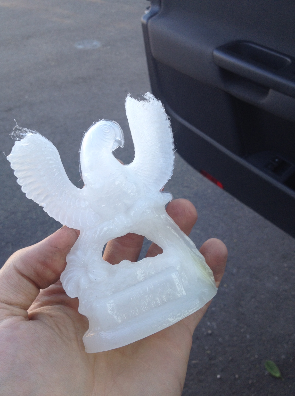
First Part out of the Molder
I got access to a set of vintage molds from an actual mold-a-rama machine (the macaw) and put them on the machine. After two misfires the third one came out pretty good. A little incomplete on the wing tips. I need to setup multiple regulators on the air supply, that way I can run the injection piston at a higher pressure than the rest of the system, allowing me to fill the molds faster.
Sealing it
With the melt tank installed and the pump body assembled, I can now start fitting the injection cylinder to the tank. The large (50mm!) air cylinder moves a piston in the pump body to draw in molten plastic, and then force it into the mold cavity. The piston seals to the pump body with a cup seal. The original mold-a-rama actually has no seal on the piston itself, it seals around the shaft of the injection cylinder, the seal can be seen here:
This is the injection ram of the mold-a-rama. The seal is in the center of the picture on the aluminum plate, the fiberglass insulation is covering the tank.
Installing the seal was a real bear. The cup seal is sized for a 3″ cylinder, it flares out to ~3.25″ OD to press against the cylinder walls. I needed to compress is to fit it into the cylinder. Softening the seal really had no impact on it’s flexibility, what I really needed was a piston ring compressor. Lacking that I used several daisy chained cable ties. That still didn’t work well so I used some plastic tools to push the seal in.
I wasn’t sure what to use to insulate the melt tank until a fateful trip to Lowes. In the pipe insulation section I found this self-adhesive aluminum foil backed foam tape. The adhesive holds up to the tank temperatures, and the heat radiating off the tank is noticeable reduced (as measured using the calibrated portion of the back of my hand).

I looked long and hard for a plastic water tank that was compact, but had a large enough opening to fit the water pump through. The water pump is supposed to be submerged in the water tank, this will extend the pump life by keeping it cooler. I gave up on finding a plastic tank and made a metal one myself. The body is made from 6″x6″x.120″ wall aluminum tubing with a water jet aluminum flange and lid. A cable gland seals around the power cable. The gold cylinders sticking out from the flange are rivnuts, those along with thumb screws will allow tool-less removal of the water tank lid for refills. I plan to add a sight glass later on so I can check the water level with out removing the lid.

The mount for the mold delivery cylinder (the one that pushes the finished plastic part into the retrieval bin) is made from a small piece of 1″x3″ aluminum tubing welded to the top frame and a shaft collar.
The lower half of the aluminum shaft collar is welded to the back of the rectangular tubing, the upper half is free and is what clamps onto the cylinder.

The molder is pretty awkward to move around as it doesn’t sit on a wheeled base. I added handles to each side to make moving it a little easier. The first set of handles I got from McMaster were plastic, thinking the machine couldn’t weight more than 100-150lbs, it turns out I forgot to take into account two very heavy items: the water chiller and the compressor. After putting those in, the machine weights closer to 200lbs. The plastic handles were quickly swapped out for some beefy aluminum ones. I’ll still probably move the machine with the compressor and chiller removed, but now I have a lot move confidence in the handles while moving the machine.

And finally, before I go, a sneak peak of the new molds!

Light Assembly
Things really started to come together this week. After spending a solid month machining, cutting, tapping, and welding parts and sub-assemblies, I began putting it all inside that empty 80/20 frame.
The air tank went in first. I am not completely happy with the mounting method, but it’s good enough for now, I’ll most likely make some bent brackets for it later on. The black board on the bottom is 1/2″ plywood laminated to a thin ABS sheet. It’s cheaper than solid plastic sheet and it gives it a finished look.
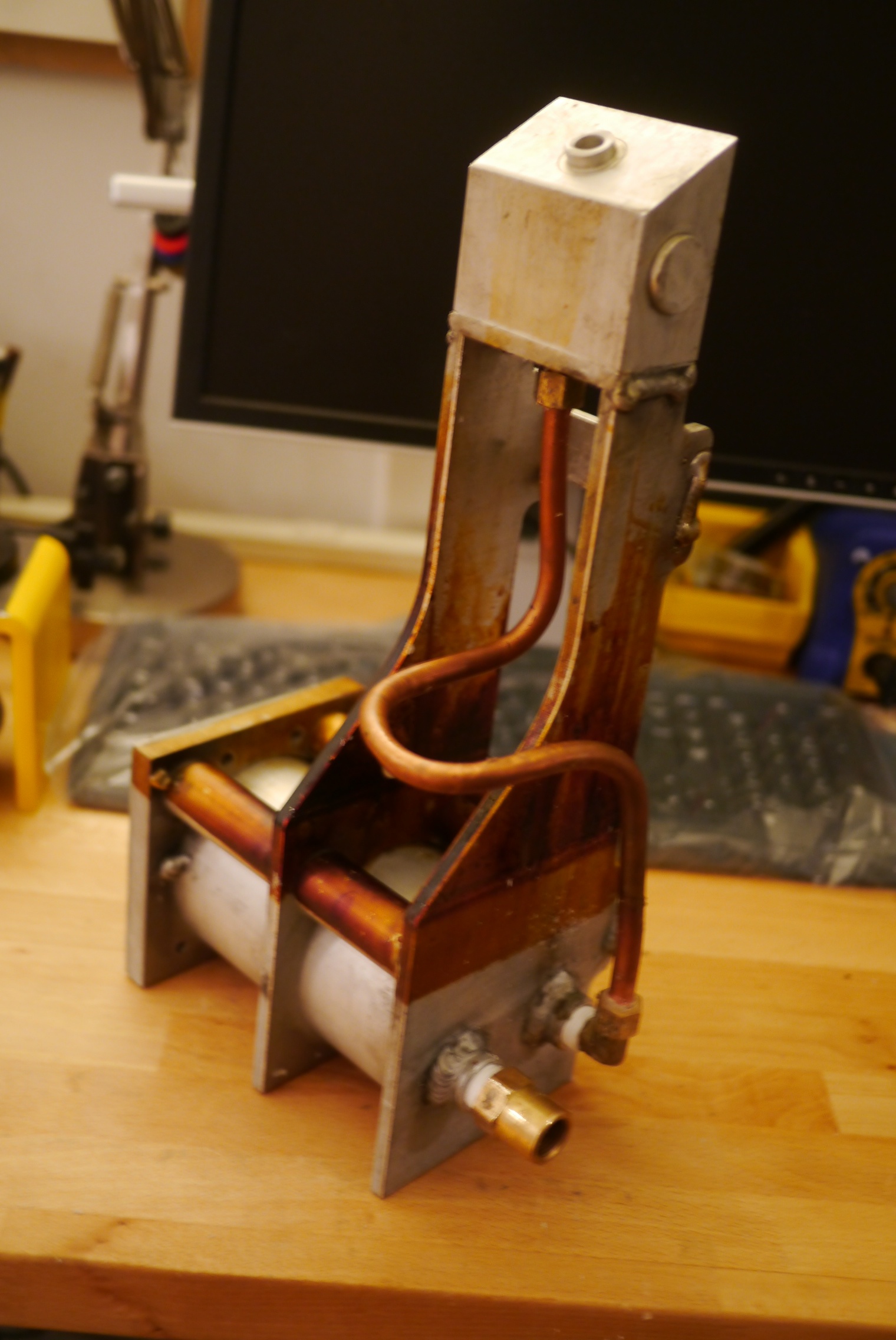
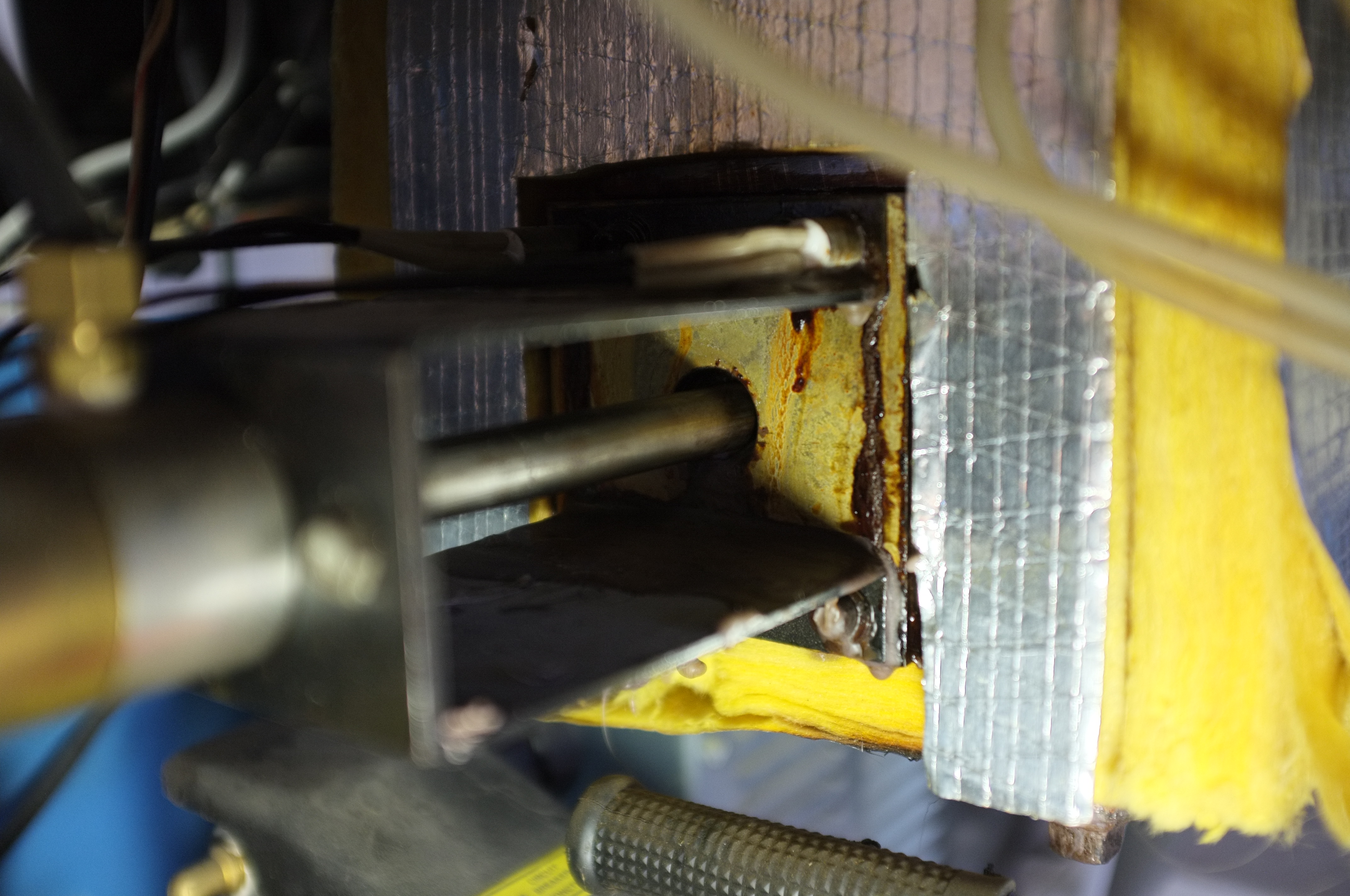
I started assembly of the pump body next. The pump body sits inside a tank of plastic material. It serves several functions. Cartridge heaters slide into the smaller 1″ OD x 0.25″ wall aluminum tubing, heating the entire weldment, and thus melting the plastic around it. The larger tube is the pump cylinder, inside that is a piston with a cup seal. When that piston is pulled back, it sucks molten plastic into the pump via the check valve (the cylindrical brass fitting). When the piston extends it forces molten plastic up the copper tube and into the valve body up top. It’s basically a 3″ aluminum syringe.
In the real mold-a-rama this is a one piece casting (it also doesn’t use the check valve). Since I don’t have access to an aluminum foundry, making it from plate and tube was the next best option.
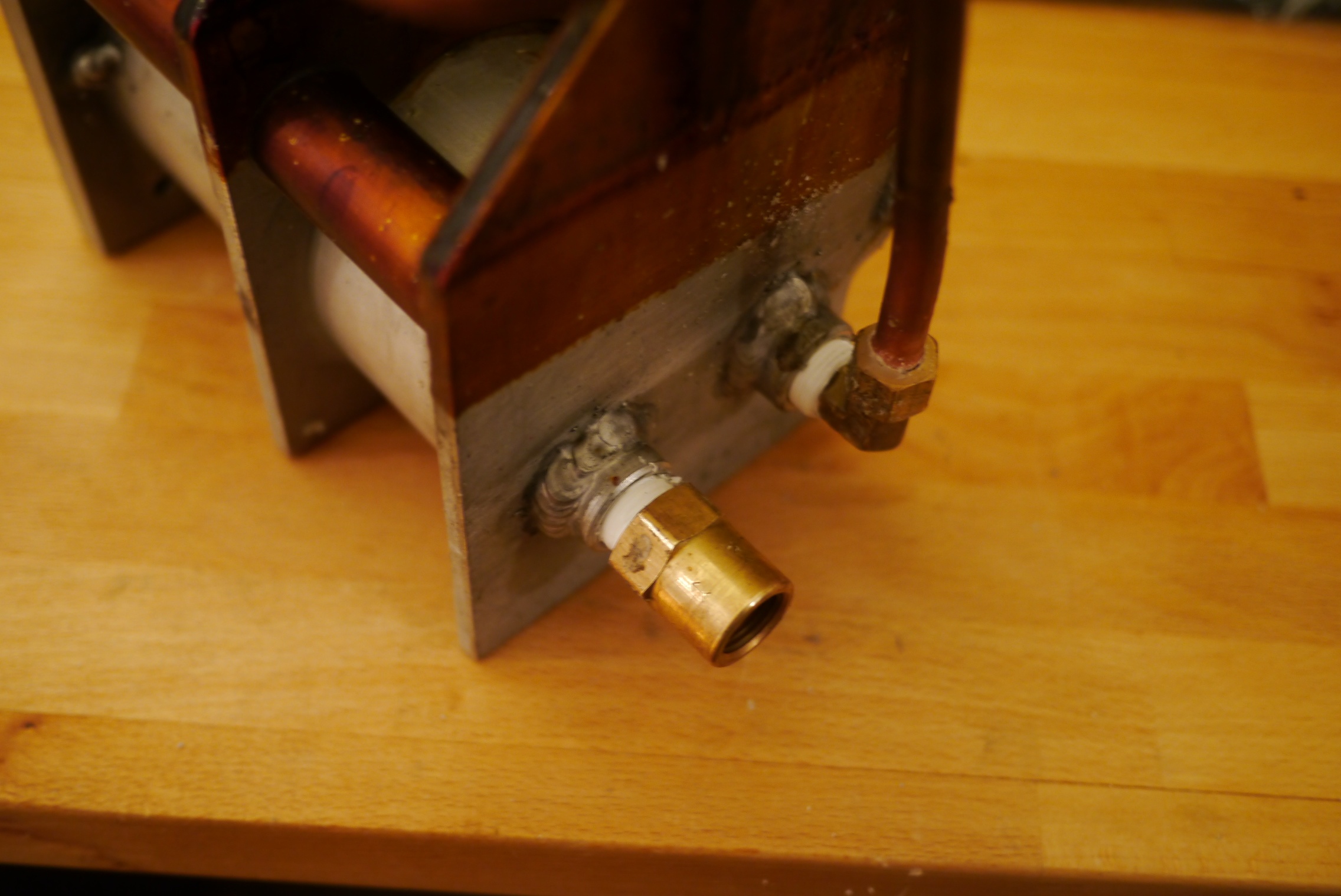
I started with the base weldment and added the valve body on top and fittings on the side.


Next I bent up a piece of soft copper tubing. Side note: during manufacturing, drawing the copper to size work hardens it making it very hard, annealing it brings back it’s ductility (soft and bendy), if you accidentally buy hard copper you will not be bending it without splitting it open.
Also make sure you buy the correct size copper tube. Copper tubing is sold both in 3/8″ ID and 3/8″ OD sizes. The brass fittings are 3/8″ compression type and are meant for 3/8″ OD tubing.
I thought bending the tube was going to be really tough, as I have two distinct points I need to reach, so the copper needs to be bent within ~1/16″ the correct dims, otherwise it won’t sit correctly in the fittings. I made some careful measurements, bent in increments, and left myself some extra length on the ends to trim to size. Surprisingly I got it right on the first attempt.
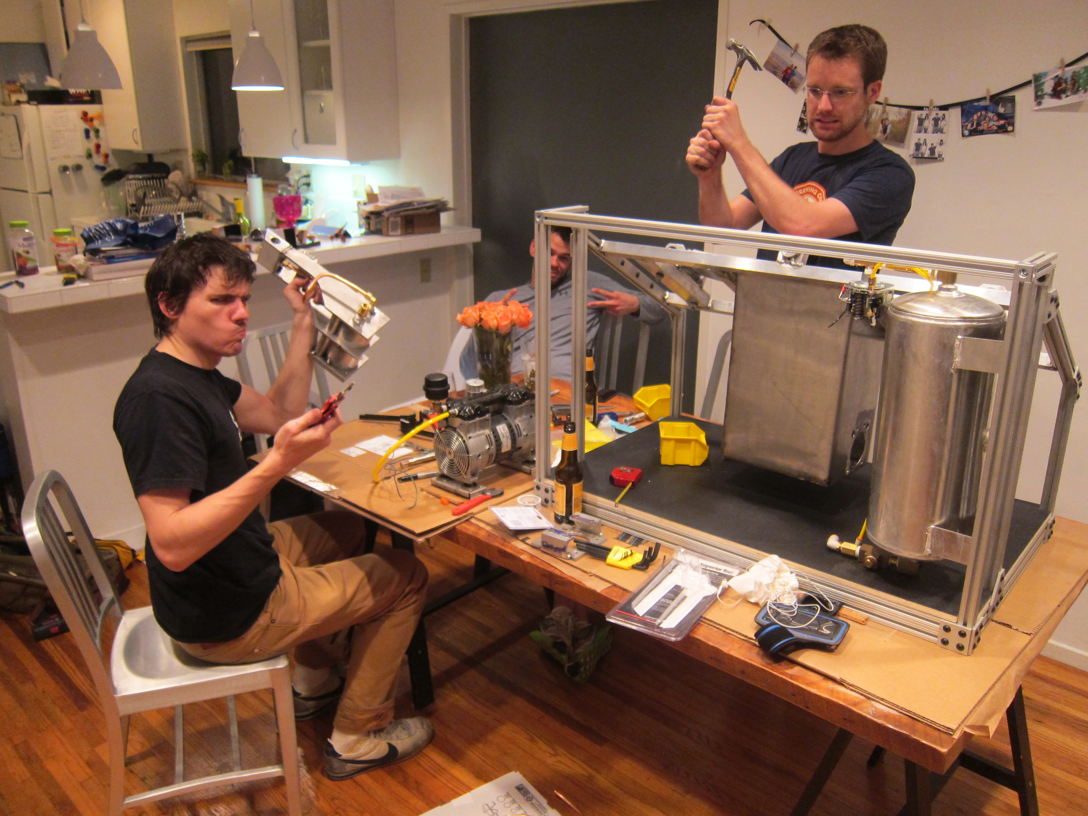
Unfortunately the only picture I have of the completed pump body is in this awesome photo:
Up next to install:
- Plastic injection cylinder and mount
- Mold cylinders and mounts
- Compressor
- Chiller
Protect Yourself! Building a Machine Cover
After nearly getting a serious burn from flying 240 degree plastic, I decided the molder’s cover needed to be moved up higher on the priority list:
I think it’s actually closer to the middle of the priority list…
The original Mold-a-Rama used a bubble top to protect the users (fitting for the 1950s theme of the machine). Here’s good guide on making one yourself:
http://www.recumbents.com/wisil/bubbles/hpvbubbles.htm
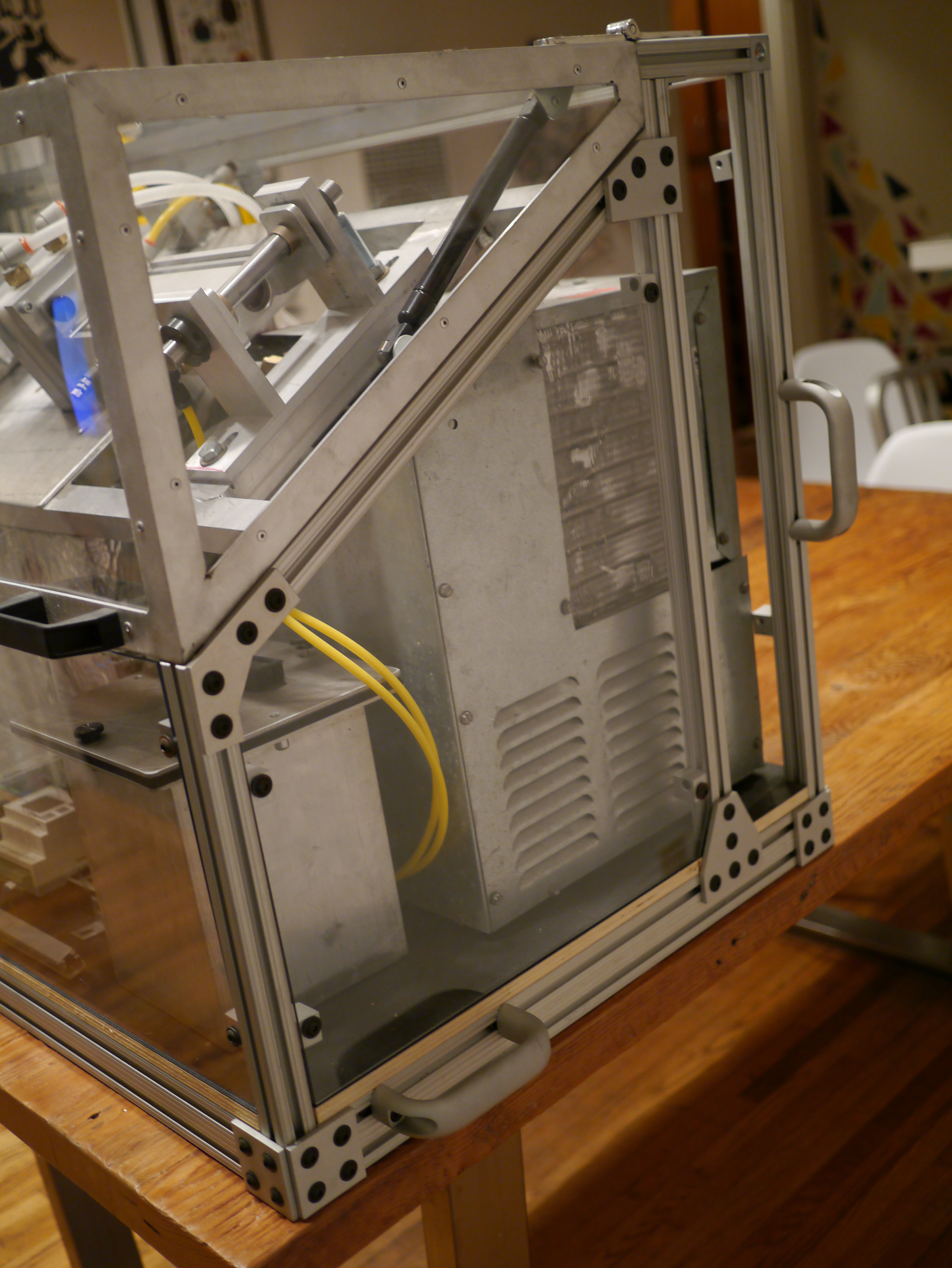
Since my machine is decidedly more industrial, I went with an aluminum frame made of 1″ x “1 x 1/8” aluminum angle with polycarbonate panels. Polycarbonate (aka lexan) is a better choice for a machine enclosure than say acrylic due to its higher impact strength. Acrylic will shatter upon impact. My molder’s cover completes the square profile of the machine (in green below). It hinges at the back and will latch (somehow?) in the front.

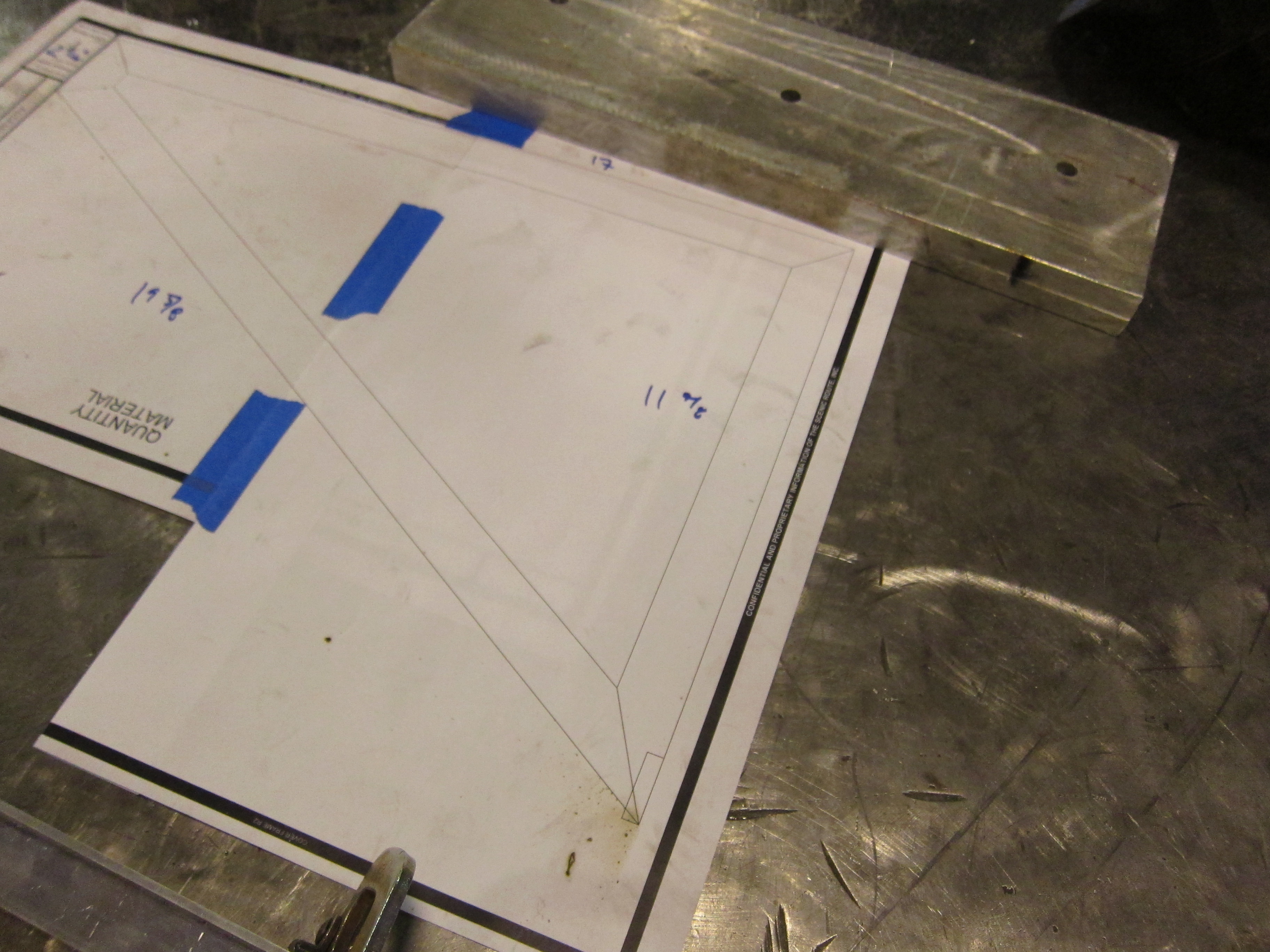
After cutting the stock to size, I printed out a 1:1 outline of the sides.
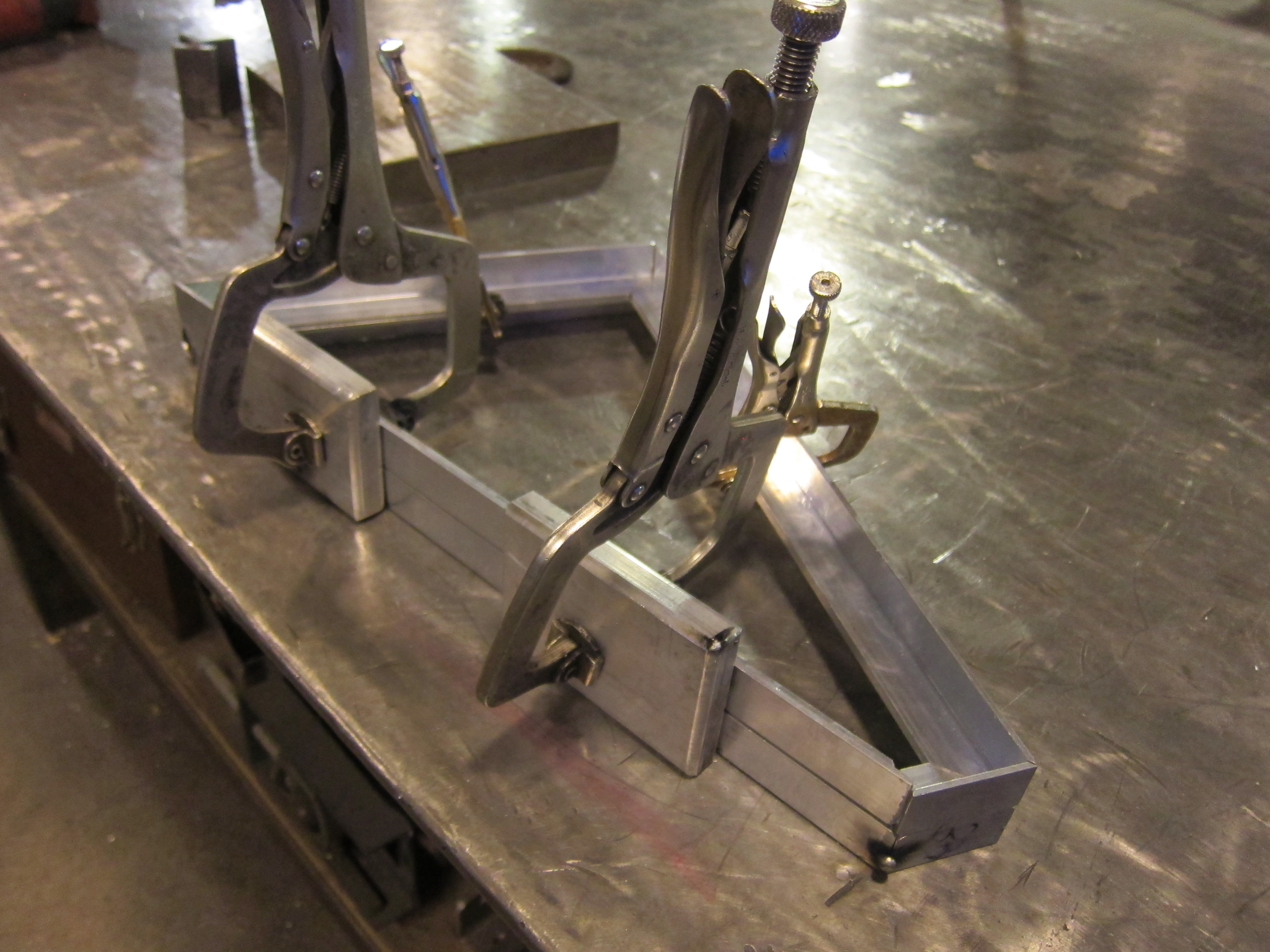
I welded one side, and then use that part as a jig for the other side.
The two halves were welded tether with supports spanning the middle. I used an angle grinder and roloc disks to dress the welds. Since I wanted smooth joints, I needed to put a heavy bevel on the ends with the joints before welding. This allows you to have a smooth joint while still having weld remaning to hold the parts together.
After finish welding the frame, I cut to size the plexi panels on the table saw and peeled back a little of the protective film.
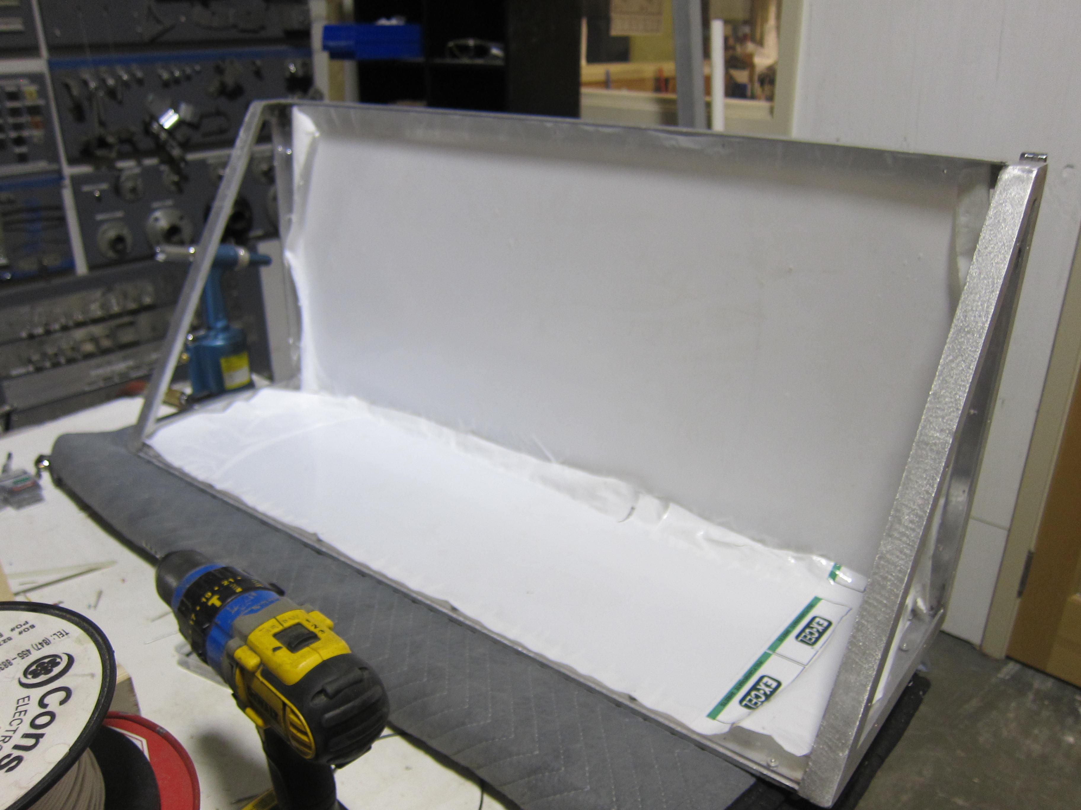
Pop rivets are used to hold the panels to the frame. I used a washer on the back of the plexi panel to keep the rivet from pulling through.
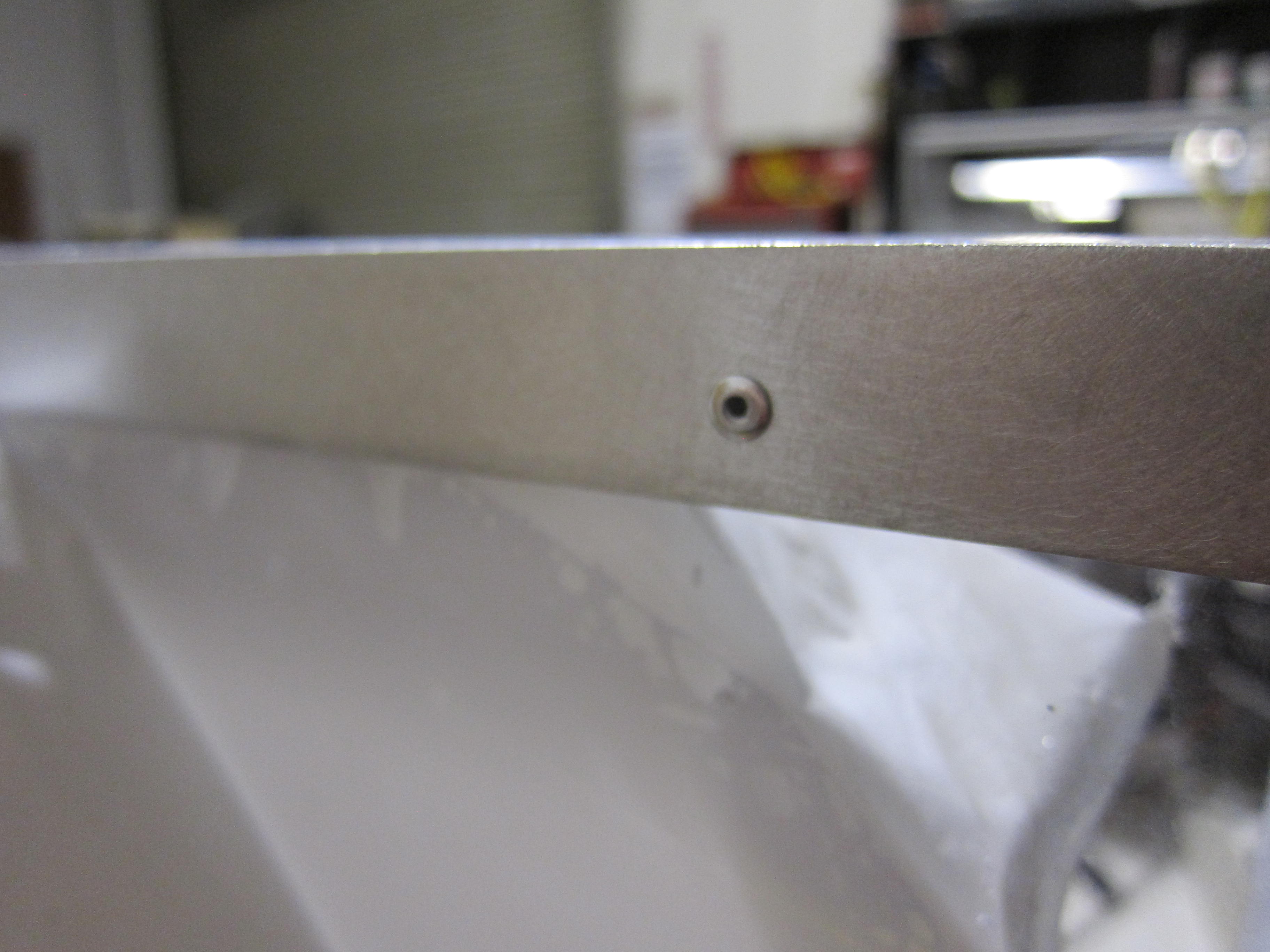

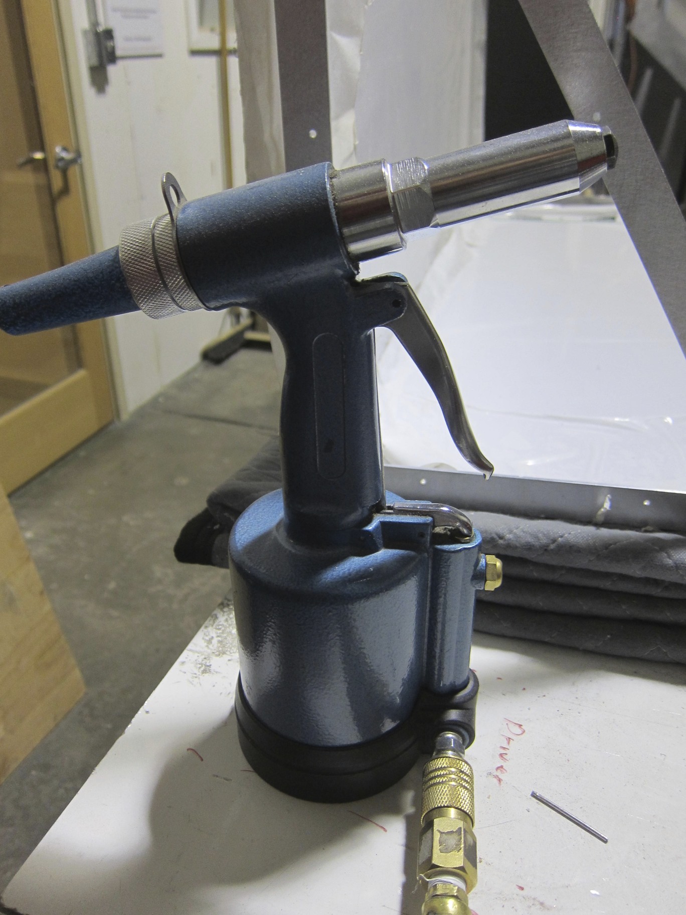
For this project I got to borrow a pneumatic riveter. These are SO much better than a manual riveter. Since you don’t need to apply nearly as much pressure, it’s much easier to get the rivets to sit flat. Also less hand fatigue, double win.
That’s it for the cover.

