Mini Lathe PWM Controller Repair CJ0618

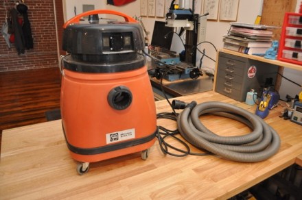
A few years ago I picked up a broken open box mini lathe from a local tool importer via Craigslist. It was advertised as an unbranded 7×12 digital mini lathe with only a picture and a brief description. I knew it would be the perfect addition for my home shop if I could get it working. It turned out to be a CJ0618B mini lathe, originally manufactured by Real Bull Machine. This lathe is relatively uncommon compared to the ubiquitous Seig C2, making it difficult to find information about it online. It seems to be extremely similar to the Seig C2, though with a lower build quality, fit, and finish.

While the slightly more common CJ0618A model comes with a version of the classic KB controller, the CJ0618B has a custom pulse width modulation (PWM) controller. This PWM controller appears to have closed loop spindle speed control, a feature rarely seen in these low-end mini lathes.

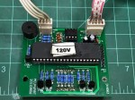
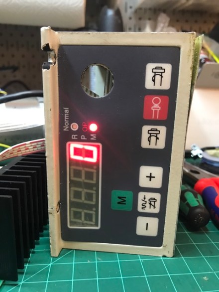
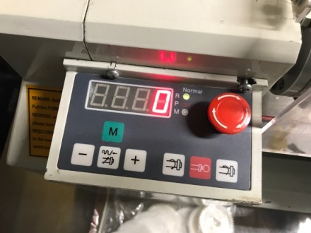
When functioning properly, pressing the start button on the lathe will power a display that indicates RPM, which can be adjusted with the keypad. The spindle motor would start after pressing the forward or reverse buttons. However, when you pressed the forward button on mine, the lathe would do nothing for a few seconds and then beep loudly and flash ‘A001″ on the display. Fortunately the lathe came with a small booklet that explains the operation and fault codes of this controller. This was rather lucky, as I could not find a pdf of this online despite using all my google-fu. I scanned a copy and put it up here:

https://www.docdroid.net/SDUalO1/special-instructions-for-cj0618b.pdf

According to the manual, “A001” is an underspeed error. This occurs when the controller is trying to start the motor, but is either seeing no spindle rotation, or a lower RPM than it was commanding. In my case it was the former.

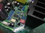
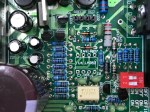
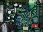
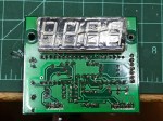
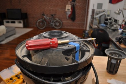
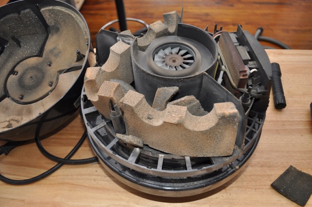
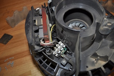
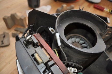
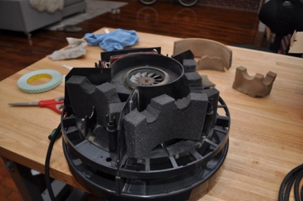
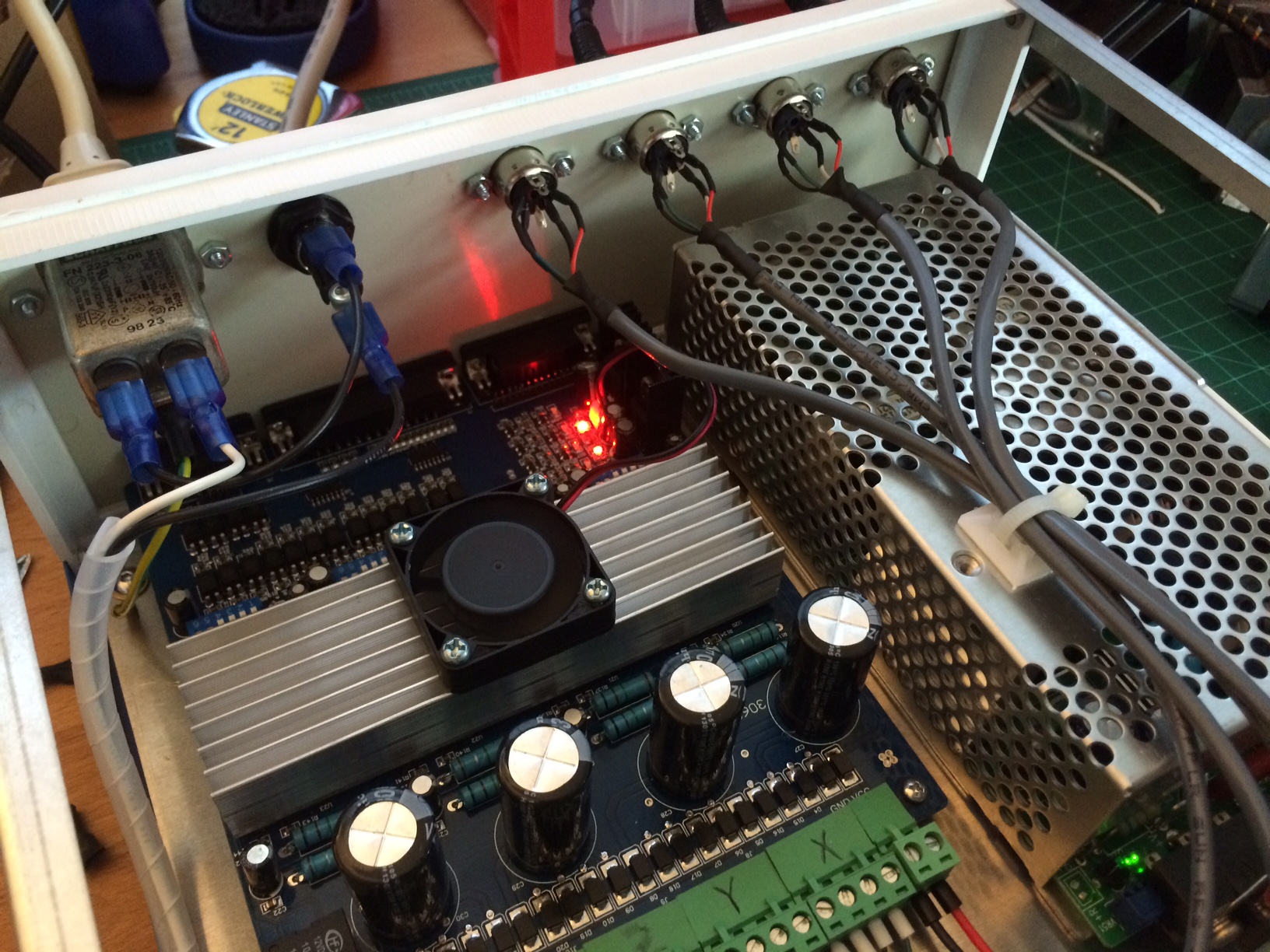
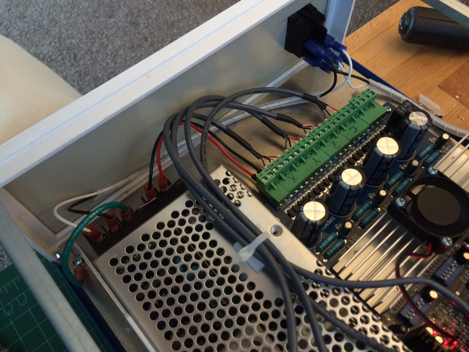
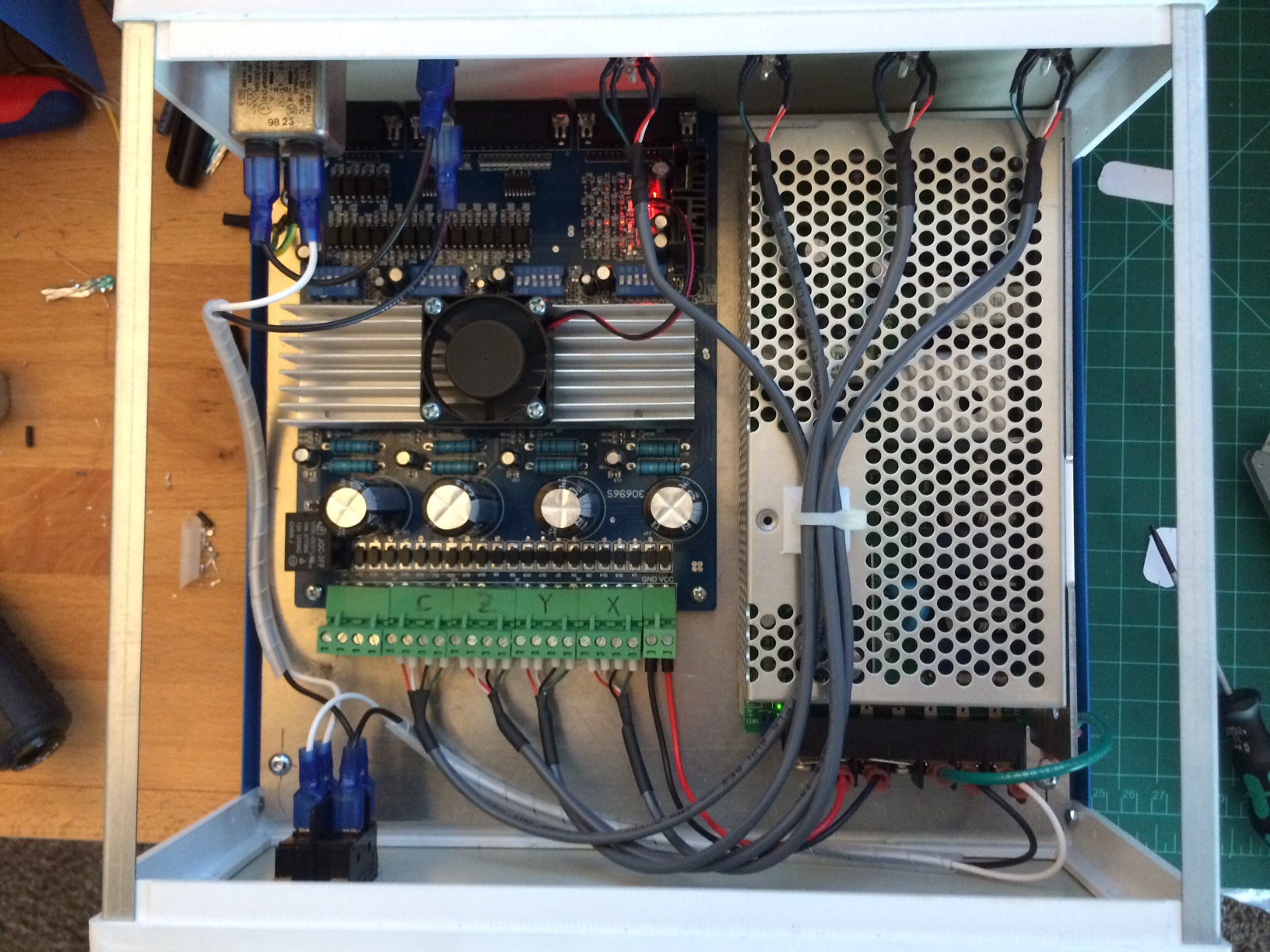
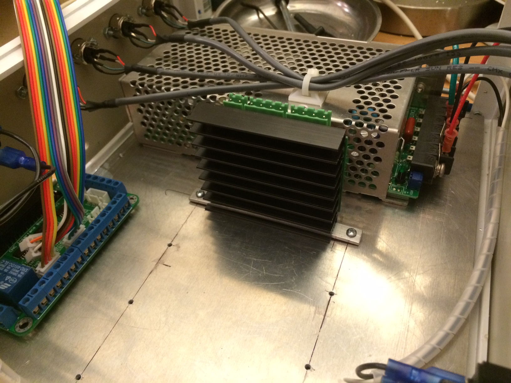
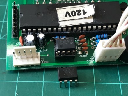
I took the controller off the lathe to look at the internals and found two printed circuit boards (PCBs): one appeared to be for logic and the other for power. The logic board was labeled MCUPWM8T and had a microcontroller (MCU), a few through hole components, an unmarked IC, and the 4 digit 7 segment LED display. It had three harnesses attached to it, one from the tachometer sensor, one for the buttons, and one going to the other board. The other larger board handles the mains power and performs the DC conversion and switching, labeled KPWT-600B. There were no obvious smoked or failed parts on either board, so identifying and fixing the failure would take a lot more digging.


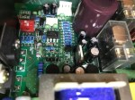
I took a look at the the overall layout of the power board to get sense of what was going on. Based on the components and their general location, I determined the following layout broken down by key functions:

ControllerLayout

Power Supply

Much of the board area is dedicated to converting 120 VAC into 5 VDC,12 VDC, and 107 VDC out. The 107 VDC line is created using a large bridge rectifier off mains power and a large filter capacitor. The relay coils are driven by a dedicated 12 VDC tap on the transformer and small rectifier. The 12 VDC of the logic ICs is created from a 18 VDC tap off the transformer. A 78L12 voltage regulator generates the 12 VDC line for the logic ICs. This regulator feeds a LM7805 regulator that powers the microcontroller. My guess for why they have both a 12 V tap on the transformer and a 12 V voltage regulator is so that they could use a smaller voltage regulator to feed only the logic ICs instead of the higher current relay coils.

Motor Control Relays

The power board has two relays: one switches the positive and negative leads going to the motor to control spindle direction and the other is a braking relay. When the braking relay is activated, it disconnects the motor from the controller and shorts a 10 W resistor across the motor leads. This load causes the motor to rapidly brake, slowing it much faster than if you were to just disconnect power and let it freewheel. This is especially useful if you have a large piece of metal in the chuck, as the chuck stops almost instantaneously.

Power Switching

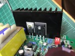
This circuit is the heart of the motor controller.   Pulse width modulation (PWM) is a way to control the speed of a motor by sending short pulses of a constant voltage, rather than raising or lowering the voltage. This allows the motor run at a slow speed while still providing sufficient torque. This is a pretty simplistic explanation, go here if you want a more in-depth answer. The MOSFET is driven with a gate driver, a TLP250 from Toshiba. This IC both isolates the microcontroller from the high voltage MOSFET and switches the MOSFET with a higher voltage and current than the microcontroller could. There’s also a large diode mounted to the same heatsink as the MOSFET. This appears to be a fly back diode to protect the circuit from back EMF generated when the motor is powered off.

Overcurrent Protection

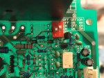
This board uses a LM358P dual op amp to implement the overcurrent protection functionality. One side is used as an amplifier to amplify the voltage measurement taken from a current sense resistor on the controller output. This voltage is very small (<0.5V), which is why the amplifier is necessary. This voltage is proportional to the current draw of the motor; the higher the current draw, the higher the voltage. The other side is used as a comparator to compare the amplified current sense voltage to a reference voltage. There’s a small set of DIP switches that allow you to set the max motor current before the overcurrent protection kicks in. The output from the comparator will either turn on the green “normal” LED and send Vcc to the gate driver IC, or will turn on the red “OP” LED and cut off Vcc to the gate drive IC.

Power Board Control

Fortunately the connector pinout between the logic and power board was labeled so I could pretty easily see how the logic board controls the power board.

IMG_1980

The power board supplies 5 VDC and ground to the logic board. The logic board returns a PWM signal and two relay control lines. The logic board also reads the input from the optical sensor mounted to the spindle and converts it to RPM. Since the spindle was not rotating, possible failure modes include

  • Logic board not outputting the PWM signal
  • Power board not switching MOSFET based on the PWM signal
  • MOSFET is switching, but isn’t receiving voltage from power supply
  • MOSFET is switching, but voltage is not making it to motor

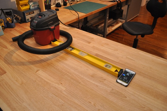
Measuring a PWM signal is pretty easy if you have an oscilloscope. I didn’t have one, so I connected the output to an Arduino and wrote a simple sketch to confirm that is was outputting a PWM signal. I later realized that my multimeter, a Fluke 177, has the ability to measure a simple frequency signal like this.

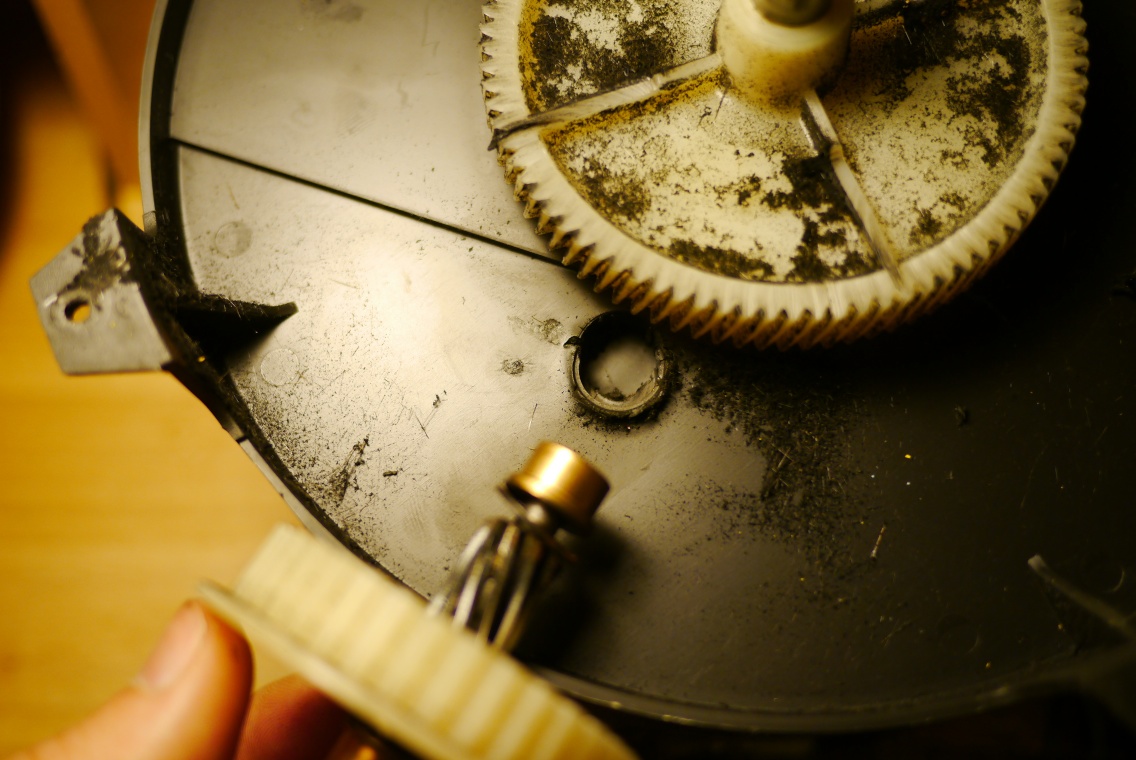
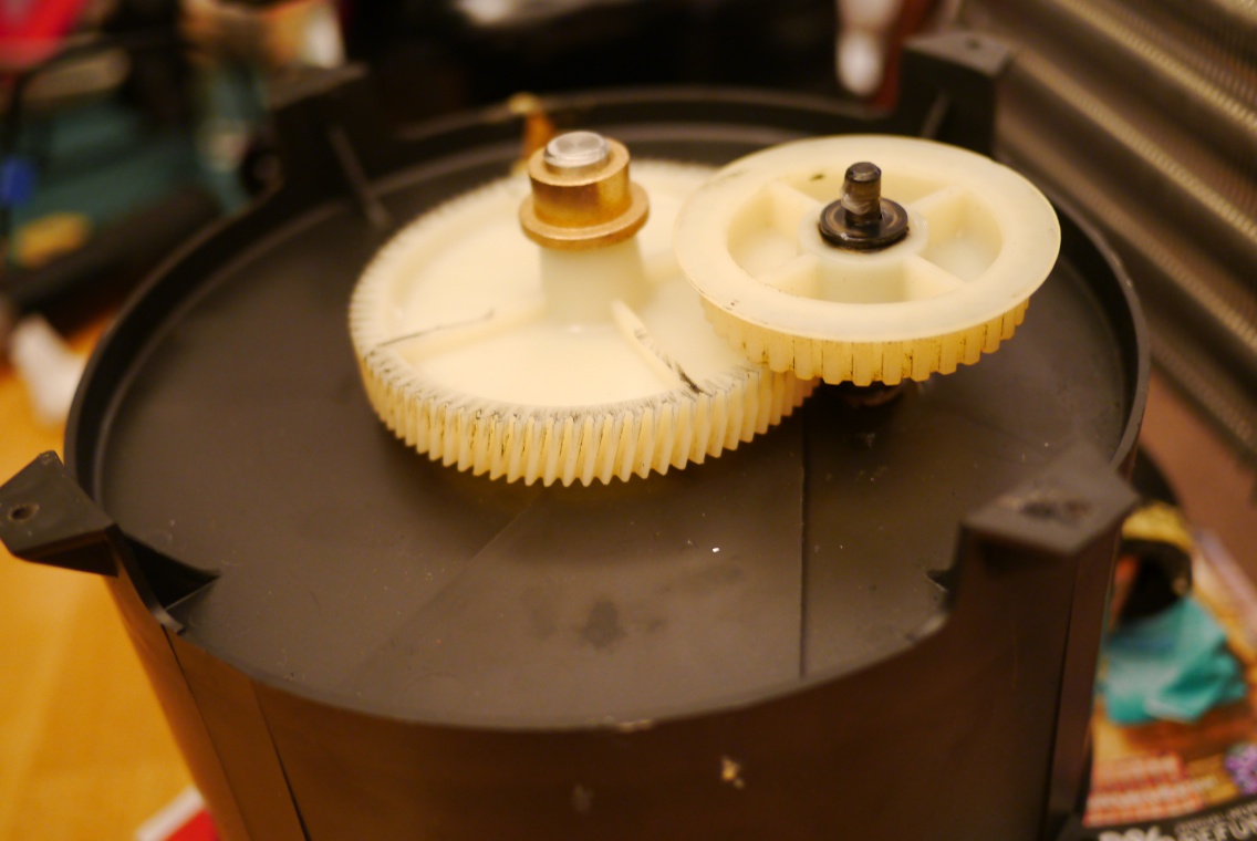
I inspected the RPM sensor mounted to the spindle and found a broken trace on the PCB, which I fixed with some 30 AWG wire. The tachometer sensor is an optical slot switch and was marked as WYC H12A5. I measured the output and found it to be very weak, outputting  <1 V when unblocked. I replaced the switch with a Sharp GP1S53VJ000F optical switch.

IMG_1985.jpg

While these sensor problems might have been problematic later on, they weren’t the cause of my issue, as the motor wasn’t even attempting to rotate. It seems like the microcontroller will wait for 4 to 5 seconds before throwing the error code. If your lathe turns on, but doesn’t indicate an RPM on the display, and shuts off after a few seconds I would check the output of this sensor at the logic board.

Since the PWM signal was being generated correctly, I decided to check for proper voltages around the board. I found the data sheets for the IC’s and located the Vcc pins for each. I measured around 8 VDC at the gate driver, but the data sheet specified a minimum of 10 VDC. I traced it back to a bad 12VDC regulator and shot off an order to Digikey. A few days later I replaced the failed regulator and powered the controller on.

IMG_1981

The input at the logic ICs was now a steady 12 V! My joy was short lived as the controller still gave me the A001 error. However now the red overcurrent protection (OP) LED was on. What was odd was that the LED turned on the moment the controller was powered on. This behavior made me suspect there was something wrong with the circuitry that activates the OP LED, because the light was turning on with no current having gone through the motor.

IMG_1982

I traced more of the circuit and found that the op amp output controls power to the LEDs as well as switching power to the gate driver IC. This ensures that the motor stops when the overcurrent protection is activated. I used a digital multimeter to measure the pins of the op amp and found the voltage comparator section of it was not working correctly. The non-inverting input was larger than the inverting input, so the output should have been high, but was reading low. This was causing the overcurrent protection to be activated. Another order to Digikey and I had a new TI LM358P op amp.

When the controller turned on I was greeted with a green LED and no red OP LED! I tried once more to fire up the motor, but alas A001 was staring back at me again.

IMG_2065

At this point I started diving deeper into the board to create a schematic of the entire circuit. Despite only being a single layer PCB, this proved difficult because the components are packed very tightly and there are many traces that weren’t visible unless the components were desoldered. A few days of on and off troubleshooting and I began to suspect the gate driver. All the other components between the output of the gate driver and the MOSFET gate seemed fine, but there was never any voltage on the gate pin when the controller was attempting to start up the motor.

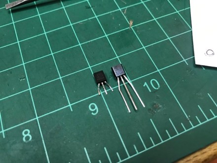
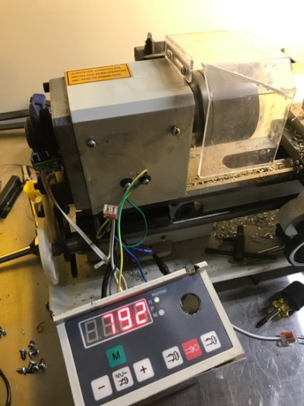
The original IC, Toshiba TLP250, has since been discontinued. You can still get them on eBay from China, but I didn’t really want to wait that long. After a little bit of research I found Toshiba had a new gate driver IC, TLP351, that is pin compatible. Another Digikey order later and I had a replacement IC. At this point I wasn’t expecting much given the history of debugging this PCBA, but when I turned on the controller, the motor sprang to life! It was quite a thrill after several weeks of working on this.

I began to play with the motor and speed settings and noticed a weird issue. I wasn’t able to get the rotation direction to reverse. On a lathe sometimes you want the spindle to turn one way or the other, depending on which side of the part your cutting tools is. On this controller if you press reverse while the motor is spinning, it is supposed to ramp down in speed, stop, and the ramp back up in the opposite direction. On mine it would ramp down, stop, and then ramp up in the same direction.

I also noticed the direction control relay would close when the controller was turned on, but would never open when it should have. The same was true of the brake relay, the motor coasted to a stop, instead of being shorted to the braking resistor.

I started to dig back into the power and logic board to see how the relays were controlled. I checked for 12 VDC on one side of the coil and found it on both relays. Tracing back the path to ground it seems the relays are grounded at the logic board. Taking a closer look at the logic board, I found a 8 pin DIP IC with its part number marking intentionally removed, which made investigating this IC challenging. This device was the interface between the microcontroller output pins and the relay coils path to ground. I traced back all the pins and came up with the below schematic:

MysteryIC

Using the schematic, it’s evident that this is an IC that controls two 12 VDC relay coils by switching them to ground, runs on 5 VDC, and takes a logic level input from a microcontroller. I also noticed that the input from the microcontroller went to two pins each. I thought this might be some kind of Darlington array transistor, but the pinout didn’t match anything that I could find. Searching around online I stumbled across a list of logic ICs and sorted them by pin count until one caught my eye: a dual 2-input NAND 30 V / 250 mA relay driver. Based on the data sheet, the pinout didn’t match exactly, but it was close.

MM74C908N

A little more searching and I found it’s not uncommon to use logic gates (AND, NAND, OR gates) to allow a microcontroller to switch a high current load, like a relay or light. Eventually I came across a NAND gate that matched the pin out: TI SN75451BP Dual Peripheral Driver.

IMG_2059

One last order to Digikey and I had a fully functional lathe controller!

IMG_2026

Total parts replaced:

  1. 78L12 12VDC voltage regulator
  2. TI LM358P dual op amp
  3. Toshiba TLP250 gate driver
  4. TI SN75451BP NAND Gate
  5. Optical slot switch

Given all of these failed components are ICs, I would guess that some kind of voltage spike or power surge occurred and blew all these components simultaneously.

This repair tested the limits of my board troubleshooting and repair abilities. It was frustrating at times to find and fix issues only to reveal more issues, but I am glad I stuck with it as I now have a fully functionally lathe.

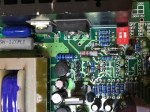
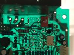
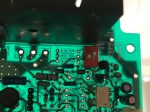
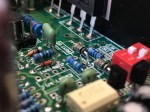
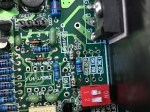
Here are some more photos of the PCBs, some with the components removed so you can see the traces better.


Fein Turbo II: Foam Repair and HEPA Upgrade

More and more of my projects involve cutting wood with power tools. Cutting wood with power tools creates an enormous cloud of dust. My workshop is in my living room. Given all these facts, I decided my mini Shop-Vac wasn’t cutting it, and started looking for something a bit more robust.

As I began researching different vacuums, I found that high-end vacuums were generally referred to as “dust extractors”. I’m assuming this is to convince yourself that the $700 you just spent on a large plastic box on wheels was justified. Besides the price, high-end vacuums usually differ from Shop-Vac type vacuums in several ways:

  • Quieter. Mufflers on the exhaust and sound dampening foam reduce noise.
  • Better filtration. HEPA filters combined with sealed motor housing means fewer dust particles leak past the filter/housing.
  • Separate cooling for motor. Cheaper vacuums use the suction stream to cool the motor. If the suction stream stops while the motor is running, say due to a clog or collapsed hose, the motor will overheat and eventually burn up. High-end vacuums have a separate stream of air that is fed to cool the motor. An additional benefit is that the motor is being cooled with a clean stream of air rather than the exhaust from the suction hose. In theory this should result in a cleaner, longer lasting, motor.
  • Auto-start. Convenient feature that allows you to plug in a tool and start the vacuum when ever the tool is turned on.
  • Adjustable suction. Useful when hooking the vacuum up to sanders.

I looked at options from Festool, DeWalt, Fein, and Nilfisk. After some comparison shopping, I realized I had Festool dreams on a Shop-Vac budget.  Per usual, when I want a high end tool I check the used market. After some searching on craigslist, I found a great deal locally on a used Fein Turbo II. It checks the box on just about every feature listed above.

DSC_0840

Once I got it home I noticed that it had some white over spray on it.

DSC_0843

I used Novus #2 fine scratch remover to take off the paint. The small bits of paint came off pretty easily, but the larger ones took some scrubbing. To give the plastic back some of its luster, I followed up with #1 plastic clean & polish. The lower orange plastic body didn’t have the same level of overspray, so I just used Armorall cleaning wipes.

DSC_0848

DSC_0850

After cleaning up the vacuum, I did a quick comparison of the noise generated by this new vacuum and my old mini Shop-Vac and the difference was astounding. The Fein sounded like a muffled household vacuum, the ShopVac sounded like… your typical wailing Shop-Vac.

Since I don’t have a legit SPL meter, I used the next best thing: a free app on an iPhone. The mini Shop-Vac came in at about 82 dB, comparable to a garbage disposal or blender. While this setup is far from laboratory-like conditions, the measurement from the Fein vacuum at 68 dB did match well with vacuum cleaner noise levels. After performing this test I found advertising material for the Turbo II that list the noise level at 57.8 dB from 3.5 ft away. In my setup, the iPhone was 2 ft from the vacuum.

During the sound testing, I noticed small bits of crumbling gray foam on the table. I tracked the source down to the exhaust port of the vacuum. A little searching online showed this to be a common problem for older Fein vacuums and was attributed to foam inside the motor housing deteriorating and being blown out the exhaust.

I started by removing the float and float cage from the bottom of the motor.

Next up was the motor cover. To reach the screws buried deep in the motor housing, I used a long Phillips bits in a screwdriver handle. Note to self: add long screwdrivers to my wish list.

DSC_0150

Removing the cover revealed the extensive use of foam by Fein to muffle exhaust and motor sounds. No less than 4 different areas were covered in varying thicknesses and shapes of foam. The old foam was brittle and crumpled at the slightest touch, likely due to a combination of age and heat from the motor.

Peering down to the actual motor, I could see more foam fragments buried further. Removing the next layer of housing required disconnecting the two leads going to the motor. One is a spade connection and the other is in a terminal block.

DSC_0162DSC_0160

The last crumbling foam part was finally visible. Surprisingly, the foam around the actual motor was still intact and resilient.

DSC_0167

My first instinct was to order a replacement foam set, but alas Fein has discontinued many of the spare parts, including the foam.

Looking closer at the intact foam around the motor, it reminded me of the sound absorbing foam used to line the inside of recording studios. I checked McMaster and some other online retailers, but couldn’t find the correct type and thickness. Luckily a local foam supply store carried both thicknesses I needed, and it was super cheap.

DSC_0175

Based on appearance and density, the foam seemed to be a close match to the foam still on the motor.

DSC_0180

I made patterns of the foam parts and cut out replacements. A bread knife cut through the foam wonderfully. The key is to use long strokes rather than a short sawing motion.

DSC_0176

DSC_0186DSC_0192DSC_0196

One of the foam inserts on the cover is retained with push nuts. These can be tricky to remove without breaking the plastic post, so I left this one in place. At the time, the foam seemed to be in relatively okay shape, but it’s recently started shedding particles. Eventually it will need to be replaced too.

DSC_0205

After reassembling the vacuum, I swapped out the fleece filter for a paper bag and added a HEPA filter. The Fein branded one costs nearly $100. A much cheaper option is the Gore CleanStream filter for Rigid/Craftsman vacuums. The CleanStream is a little bigger and lacks the positive lock feature of the OEM filter, but the friction fit around the float basket feels secure.

It’s a few inches larger in diameter, but so far there doesn’t seem to be any noticeable impact on dust capacity.

DSC_0946DSC_0947

There’s a soft rubber seal that happens to match the Fein float cage perfectly. All that’s needed is a little force to fully seat the filter.

DSC_0948

After repairing the foam and adding the HEPA filter, this vacuum is amazing. I was a little concerned that my miter saw, a DeWalt DW712, would draw too much current for the vac’s autostart function, but so far it has worked fine. My only negative for this particular model is the lack of hose and accessory storage, though Fein seems to have addressed this in the current model. I have some ideas for an add on storage solutions I might implement in the future.

Having used Shop-Vac type vacuums my entire life, I was a little skeptical about the necessity of all the features in high-end vacuums. While I’m still not at the point where I could justify any of the Festool models, the Fein Turbo series has all the features I need.


Anfim Best Coffee Grinder Rebuild

For a while now I’ve been wanting to get an espresso machine. After several hours researching machines in specialty coffee forums, I was surprised to find that the quality of the coffee grinder actually has a bigger impact to the taste of the espresso than the actual machine does. Spending a lot of money on an espresso machine and then skimping on the grinder will usually get you poor results. With that in mind, I focused on getting a good grinder first.

The recommendations online were to spend about 50% of your total budget on the grinder, which put me in the $150-200 range. I initially looked at Baratza’s entry-level grinders, but most reviews claim its finest setting is borderline usable for espresso.encore-5

Side note: If you haven’t seen them yet, Seattle Coffee Gear has an amazing range of reviews, head-to-head comparisons, and tutorial videos. They were an excellent resource when I was researching equipment https://www.seattlecoffeegear.com.

Knowing that the higher end coffee equipment tends to be more durable, I decided to look for a used grinder that would have otherwise been out of my price range. I combed Craigslist for a few weeks, but never really found anything worth looking at.

Then one day I came across an ad cryptically titled “Coffee Bean Grinder $10”. I clicked the ad and saw a filthy, broken, coffee grinder. The price suddenly made more sense. Looking closer I noticed it had a doser. This isn’t something you typically see on low-end grinders, as it’s really only needed for coffee shop/restaurant applications. There was no mention of a brand, but a photo from the back showed a label “BEST MILANO”. A quick search online dug up the manufacturer, Anfim, a fairly high-end brand from the 80’s and 90’s. The ad also said it was stuck on one grind setting. Coffee grinders tend to be simple mechanically, so I took a chance on it being an easy fix. I made contact with the seller and setup a meeting the next day.

I arrived to meet a nice, elderly women who was selling the grinder for her husband. She said they had purchased the grinder over 20 years ago at a cost of around $500. Her husband recently switched to pour over coffee which necessitated a coarser grind. This one, being stuck on a very fine setting, was destined for the garbage before the wife offered to put it on Craigslist in case someone wanted it. That someone was me. 

I took the grinder to a friend’s house and began inspecting it. The first thing I noticed was how incredibly heavy this small grinder was. Even without taking it apart, I could tell the base was solid cast aluminum with a serious motor.  Judging by the thick layer of coffee oils and residue inside the hopper, this grinder hasn’t been cleaned since the Reagan administration.

img_2719

img_2720

img_2721

I verified that indeed the adjustment collar was stuck at setting 4.

The brown stuff here may look like coffee dust, but it’s actually a ~0.050″ thick layer of coffee sludge.

img_2722

img_2724

anfim_coffee_grinder_exploded_diagram_tav03

The bean hopper (PN 702711)is removed by simply lifting it up and out of the upper burr carrier. Make sure the hopper is empty before you remove it, this model doesn’t have any kind of valve to keep beans in.

Ordinarily the upper burr carrier (PN 702740) would be removed by just unscrewing it counter clockwise. This might have been the case if someone had actually cleaned this area at least once in its life. In my case it wouldn’t budge. I probably could have used a strap wrench to unscrew it, but being without one, I grabbed a friend. With him hold the base and me grabbing the burr carrier we put everything we had into it.

Dramatic reenactment:
opening_jars

The first 2 or 3 revolutions were extremely difficult. After breaking through the coffee oil thread locker, the carrier unscrewed easily.

img_2733

The dark film at the base of the threads was acting like a thread locker, bonding the upper burr carrier to the base. It’s no surprise the previous owner thought it was jammed.

img_2736

Fortunately the burrs were in pretty good shape. Replacement burr sets are easy to come by and cost around $40.

After getting the burr carrier out, I turn my attention to the back cover. There weren’t any visible fasteners, so I assumed it was held on by a snap or clip. A fingernail at the seam allowed me to open it up just enough to see that there was a wire spring clip holding it to the base. Once you pull the cover back enough to clear the base, you just slide it down off the clip.

img_2727

img_2731

Without the rear cover in place, you get a nice view of the insides. Behind the motor shaft are the bolts that hold the doser to the housing. The white cylinder on the right is a starting capacitor for the motor. And just peaking out from the bottom is the motor (specifically the stator). This grinder is what’s know as a direct drive grinder. There are no belts or gears in the drive line, the lower burr is directly connected to the output shaft of the motor. This is typical of higher end grinders. Using belts or gears allows the manufacturer to use a smaller, cheaper motor. The gear reduction in the gears or belt drive increase the torque output of the small motor. However these components can be the source of additional break downs. More bearings to wear out, belts to break, and gears to strip. Probably less of a concern for the home user, but if you’re running a coffee shop, having a your grinder break is going to have an impact on your business.

The main bolt that holds the doser to the body is directly behind the motor shaft. It’s also the most hilariously over sized bolt I’ve seen in awhile. Getting to it from the rear opening was pretty much impossible without an offset wrench or crowfoot socket.

After staring at the problem for a few minutes, I realized I might be able to get at it with a regular combination wrench through the switch opening.

img_2741

This worked, but was time-consuming as it could only turn the bolt a few degrees at a time. I’ll replace this with a socket head screw later on, as this will allow me to use a ball end hex key to get around the motor shaft.

img_2742

Hopefully this picture gives you an idea of what I was up against in terms of the sludge. At first I thought the doser jar may have originally been a brownish orange smoked plastic, but the few clean spots suggested it started out clear.

img_2753

No vintage equipment rebuild would be complete without a dead creature buried in the depths of the machine. Ours was in the form of a spider holed up in the space between the motor and bottom cover.

img_2756

The doser rebuild started with a complete disassembly.

img_2744

img_2745

img_2750

img_2752

The weapon of choice against the coffee sludge was hot soapy water. This was pretty effective on 80% of areas. The other 20% required a scouring with a Scotch Brite pad followed by repeated soakings. As a last step I used some Novus plastic polish to remove the remaining haze.

img_2754

Right below the lower burr carrier is a pocket the drive shaft bearings sit in. I was worried about flooding this with water and not being able to dry out the bearing. So for this area, I just used a pick, screwdriver, small wire brush, vacuum, and a wet paper towel. It took about a half hour, but I managed to get it almost completely clear.

img_2764

Surprisingly the outer case was about the cleanest part of the grinder. The slight brown tint was taken off by scrubbing  with melamine foam (aka Mr. Clean magic eraser). To give you an idea how effective this material is, the small area right below cutout was cleaned in the below photo.

img_2761

With everything cleaned, assembly started with the doser.

dsc_0842

I lubricated the doser ratchet with Super Lube, as it was the only food grade lubricant I had on hand. Not visible is a small pin and spring that fits inside the doser level. This pin is the ratchet pawl that actually rotates the doser arms when the lever is moved.

dsc_0849

Before and after.

I little bit of grease on the burr carrier’s threads and it was moving quite smoothly. You can see the detents on the bottom of carrier. Those interface with the pin on the side of the grinder for holding a particular grind setting.

img_2765

Some final shots all cleaned up.

dsc_0870

dsc_0871

dsc_0873

Depending on the age of the coffee I usually have it set between 3.5 and 4.5. Sometimes I find myself sitting between grind settings, but I can usually compensate with the tamp pressure. A possible future conversion to step-less settings should take care of this.

Between the purchase price of the grinder and some cleaning materials I have about $30 invested. Using it the last few weeks has been great, and I am really glad I took a chance on this basket case. The added bonus of saving it from the land fill was also nice.

One last note, Anfim was the original manufacturer of this grinder, but it was rebranded a lot over the years. A partial list from home-barista:

  • ECM
  • Elektra
  • Francesconi
  • Grindmaster
  • La Pavoni
  • La Spaziale
  • Olympia Express
  • Pasquini
  • Stafco
  • Vibiemme
  • Wega

Snap on TECH2FR100 Techwrench Repair

How do you get a $440 torque wrench for less than 1/10 that price? Buy a broken one and fix it!

I’ve been wanting an electronic torque wrench for a long time. They are great because they are accurate at the extreme ends of the scale (unlike click type torque wrenches). Electronic torque wrenches typically have  another neat feature, they beeps and vibrate when you reach the set torque, and then tells you the exact torque that was reached.

While browsing eBay one day I found a Snap On Techwrench under $40 and with a few days to go on the auction. This particular one was listed as non-functional, even with a new set of batteries. I noticed the photos showed some extensive corrosion on the battery contacts and took a gamble it would be a cheap fix.

The torque wrench arrived and it was every bit as corroded as the pictures showed.

Getting rid of corrosion caused by leaking batteries is pretty simple. To dissolve the corrosion (potassium hydroxide) a acidic solution is needed, I used vinegar.

Before

IMG_6873IMG_6874

After

IMG_6876

A fresh set of batteries and the big moment.

IMG_6877

It works!

I used the wrench as is for awhile then shipped it back to Snap on for calibration and a retrofit to the newer battery cap style. The new style is much less prone to intermittent battery contact issues. Snap on charged a flat fee of $85 for this service.

Old style:

s-l1600.jpg

New style:

IMG_1397


Mini Molder Finished Photos!

It just occurred to me that I never put up photos of the finished Mini Molder. Here they are!

Also, if you’re wondering what’s next for the molder, wonder no more. Over the next year I plan to upgrade the machine with an automatic pellet feeder. One of the things that kept me from running the molder non-stop at Maker Faire last year was having to open the melt pot and pour in more PE wax pellets. This dropped the tank temperutre drastically and stopped the machine for a solid 45min while it got back up to temperaute .The pellet feeder will put in a little at a time, keeping the melt pot hot.

P1020993 P1020999 P1030002 P1020990 P1020985 P1030053 P1030041 P1030046 P1030028 P1030031 P1020998

Mounting DRO Scales To Your Hi Torque Mini Mill

One of the intermediary stages of my mill’s CNC conversion is mounting DRO scales to the axes. To make the stepper motor mounts I need to position the axes much more accurately than can be done by reading off the mill’s hand wheel dials. DRO’s give you good enough accuracy and repeat ability to make precision parts.

There are dozens of methods to mount DRO scales to a bench top mini mill. When designing my setup I had a few goals in mind.

  1. Minimize number of parts to be made
  2. Minimize number of holes drilled into the mill
  3. Keep everything compact and tight against the mill

Y-axis

For the y-axis I used the 8″ travel DRO version. Here the scale is fixed to the base and the read head follows the saddle. I mounted the scale about 1.25″ back from the front of the base using 10-32 hardware (fits nicely in the existing slots on the scale.) The cast iron base drills and taps pretty easily. I recommend a drill and tap guide be used here as matching the base’s 5° draft is tricky without one.

IMG_5701 IMG_5706

Mounting the scale directly to the base means the read head and saddle are no loner parallel. To account for this the bracket that connects the read head to the saddle has a matching 5° bend. The bracket is made from a scrap sheet of 0.090″ 5052 aluminum sheet. The distance between mounting holes is 20mm, all the others dimensions were just roughed in by hand. I clamped the bracket in a vise and use a crescent wrench and protractor to set the angle.

IMG_4623

The holes for the read head hardware received a slight counterbore as the included screws are pretty short (with good cause, a too long screw will dig into the scale and damage it.)

A single 4-40 screw and spacer attach the bracket to the saddle. I match drilled the hole in the saddle to the hole in the bracket as this was easier than trying to measure and mark the saddle while it was in place. You’ll want to make sure you mount the rear head far enough back on the saddle that the read head does not hard stop against the scale when the saddle is all the way forward.

IMG_5931

X-axis

The procedure for the x-axis was similar to the y-axis, mount the scale, then design a bracket to mount the read head to the mill. I decided to mount the DRO scale on the rear of the table to reduce clutter near the front of the machine. Here it seemed easier to fix the read head to the saddle and let the scale travel with the table.

I started by mounting the 12″ DRO scale on the backside of the table. The scale needs to be mounted low enough that nothing sliding across the table will hit any part of the scale. Again, 10-32 hardware fixes the scale to the table.

Re-purposing the way cover mount screws kept me from needing to drill and tap into the rear of the saddle. I took some measurements of the read head position relative to the saddle, put that into CAD, and drew up a bracket.

DRO mount

A quick check of the bracket fitment in paper.

IMG_5887

IMG_5886

Checking for fit with a paper version proved it’s value, as one of my measurements for the way cover screw holes was off by ~1mm, if I had made the bracket in aluminum first without checking I would have had to modify the bracket I had just made.

More scrap aluminum (same .090″ 5052 as before)

IMG_5888

Free handing the outline

IMG_5889

IMG_5895Fitted to the read head. I needed a 2mm spacer between the bracket and the saddle. A double stack of M6 washers did the trick.

IMG_5896

Here you can see how I was able to keep the existing way cover mount method by getting longer M6x12mm screws to replace the existing ones. The DRO bracket and spacers get sandwiched between the way cover and saddle.

IMG_5897

For now I am just installing scales on the x and y axes. I’m going to try some work arounds to get the Z height dialed in, but I may end up putting a scale on that one too.

Building a CNC Mill Stepper Driver

When I bought my Sherline mill, it came with stepper motors, but no driver box. The drive box takes the output from a PC parallel port (small electrical signals indicating which axis should move and in what direction).

Drive boxes contain several essential parts:

  1. Power supply
  2. Stepper motor drivers
  3. Break out board
  4. Connectors
  5. Fuses and wiring

I’m kind of particular about the control electronics of a piece of equipment. Control electronics should be layout in such a way that they are easily serviced. Nothing worst than trying to trace down a problem in a rats next of wiring. Below is as list of some practices I like to use when laying out an electronics enclosure.

  1. Components should be spaced to allow airflow around them
  2. Components should be removable without taking out an inordinate amount of other components
  3. Mount components to a removable panel, rather than directly to the enclosure
  4. Wiring should be neatly bundled, using removable wiring loom where possible
  5. Removable connectors are preferred over soldered connections
  6. Wire ferrules should be used when making connections to terminal blocks.
  7. Wiring going to a removable external panel should have extra length to allow the panel to be removed without straining connections (called a service loop)

Finding the right enclosure was probably the hardest part of this project, mostly because I had many criteria.

  1. Mostly made of metal
  2. Top should be removable without taking front or rear panel off
  3. Removable front and rear panels
  4. At least 10″x10″ and ideally ~4″ tall (based on some rough dimensions of the power supply and driver)
  5. Less than $50

I found several enclosures that fit a few of the requirements, such as:

Par-metal table top series. Nice, but too much money.

20s01

Circuit Specialists EM Series Price is right, but a little too tall.

em-04-0The one I settled on was from eBay, but I also found it on amazon

$_57

This enclosure fit all my criteria. My only gripe with it would be that the front and back panel are plastic and snap in place instead of using screws.

As I mentioned above, mounting components such as drivers and power supplies to a removable panel inside the enclosure makes assembly and service much easier. Parts can be installed and wired on the bench and the panel can be placed into the enclosure in one shot. This is a pretty common practice in industrial control panels. In fact, most enclosure suppliers (like Hoffman) sell panel kits that fit into their enclosures.

I took measurements of the inside of my enclosure and cut a panel out of 0.090″ aluminum sheet. 1/4″ nylon spacers and 8-32 hardware secure the panel to the enclosure. To find the position of mounting holes, I printed out a 1:1 scale outline of the power supply and laid it down next to the driver adjusting their relative locations until I was happy with the clearance.

IMG_4384

IMG_4386

When it came to the rear panel layout I did use CAD software, as I wanted the connectors to spaced evenly and I needed to make sure I had room to run the wiring. Again, I printed a 1:1 scale drawing with the cutouts and screw holes marked, and traced that onto the rear panel.

controller rear controller inside

A step drill made quick work of the holes for the circular DIN connectors and AC input fuse.

IMG_4426

The remainder of the cutouts were made on the mill.

IMG_4428 IMG_4431

A sharp utility knife squared off the corners of this cutout for the power switch on the front panel.

IMG_4433

Skipping forward a few steps, the AC input connector and fuse has been installed and wired to the front power switch and power supply.

IMG_4434

I used 4 wire 22 gauge shielded security system cable from McMaster to make the internal connections from the driver board to the DIN connectors. Where the wires connect to the Phoenix connectors (also called Euroblocks, those green pluggable screw terminal connectors) I terminated the wires with wire ferrules and heat shrink over the cable covering.

IMG_4416

Using wire ferrules instead of bare stranded wire in a screw terminal is good practice, as the strands of wire tend to get broken in screw terminals, increasing the contact resistance.

If you’d like to learn more than you ever probably wanted to about wire ferrules and their use, see this white paper from Weidmuller.

IMG_4435

IMG_4436

A cable tie mount on the power supply neatly bundles the stepper motor cables.

IMG_4437

One last overall shot

IMG_4438

At this point I thought I was done. However, my decision to use the 4 axis all-in-one board was bugging me. It’s known to be buggy, and if one axis blew the board could be taken out entirely. In the name of making a more robust driver, I switched to individual axis drivers and a break out board.

513su4LQ-GL

The breakout board was pretty easy to mount. 4-40 self tapping screws and nylon spacers secured the board to the enclosure panel. The individual drivers where more challenging. There wasn’t enough room to lay them flat, which meant they need to be mounted on the edge of their heat sink. I thought about a few ways to mount them (screws coming up from the bottom, adhesive, pieces of all thread) before I came up with the idea of using a small strap through the heat sink fin.

Using the same 0.090″ aluminum, I machined some 3/8″x4″ straps, with 1/8″ holes for 4-40 hardware.

IMG_4463
Laying out a hole pattern to space the drivers on a 2″ pitch.

IMG_4464

First test fit.

IMG_4466

Success! The driver is firmly attached, and most importantly, I can remove the driver easily if I need to change setting on the DIP switches. An added bonus is that the heat sink can conduct some of its heat away to the aluminum panel beneath it.

Fortunately the wiring I had made previously for the stepper outputs fit fine, so those did not have to be remade.

IMG_4467

Some labels on the back finish the driver box off.

IMG_4443

IMG_4444

MKV GTI P0100 MAF Error Code Repair

I was driving my GTI the other day and noticed the engine was bucking/surging at low RPM. It was fairly intermittent, however the idle was smooth. The next day the check engine light went off, a quick scan of the OBD-II port revealed at P0100 code “Mass Air Flow or Volume Air Flow Sensor Circuit”. I was initially going to clean the MAF sensor, but after reading the VW forums I thought I should check the harness first.

I peeled away the split loom and sure enough there was a break in the ground (brown) and one of the DC voltage lines (yellow).

photo 2

The break occurred right where the harness makes a sharp 90 degree bend.

photo 1

I cut and soldered the wires back together (note to self: buy a cordless soldering iron). Being that this is an under hood repair it will be exposed to a good amount of moisture and needs to be sealed. Since I didn’t have any adhesive lined heat shrink on hand I covered the repair in RTV and slipped a piece of heat shrink over it before hitting it with the heat gun.

After mending the wires I also routed the harness sightly different than factory. Instead of going over the hardpipe and making a sharp bend, I ran the wire under the hardpipe allowing for a larger radius bend.


Gaggia Gelatiera Ice Cream Maker Repair

Last winter I saved an ice cream maker from going to the land fill.

P1020779

This is a Gaggia Gelatiera ice cream maker from the early 80’s. While small in size, it’s a very heavy italian made machine. It’s significant weight (nearly 50lbs) is due to the built-in refrigeration system. In most ice cream makers you need to either pre-freeze a water lined bowl, or use rock salt and ice to cool the ice cream mixture. This machine uses a compressor, condenser, evaporator, and refrigerant to constantly cool the bowl. The advantage being that it is always ready to make batch after batch of ice cream.

After turning it on I soon realized why it was headed for the dump. While the bowl would cool down fine, the mechanism turning the dasher made a horrible grinding noise and wouldn’t turn. While I’m not a huge consumer of ice cream, I do enjoy a good repair challenge!

The machine was remarkably easy to take apart. About 8 Philips head screws and the top cover came off.

With the cover off, the first sign of trouble appeared: a fine black powder spread around the base.

P1020787

The dasher drive motor looked okay and spun freely so it seemed the problem was coming from deeper in the machine.

Getting to the innards required removing pretty much every component from the base. To make it easier to remove all the components I disconnected all the wiring, but not before making a quick diagram.

P1020796

P1020802

With the base removed, the source of the grinding noise was pretty apparent.

P1020803

P1020805

One of the bushings on the intermediate shaft had seized and began spinning in its bore. The bore, being made of plastic, was worn into an oblong shape. This caused the intermediate shaft to become misaligned, which caused two problems. First the small metal helical gear was no longer meshing correctly with the large plastic main gear, which is why the dasher wouldn’t turn. Second, the tilted intermediate shaft caused the timing belt to rub against the main gear. You can see in the above picture where the belt cut into the gear and deposited bits of belt all over the inside case.

P1020826

The new drive belt is on the right, the old one on the left. The belt wore about 1/8″ of its width off.

I ordered new parts from my favorite industrial supplier, McMaster-Carr. New bearings for the dasher drive shaft,120XL037 size timing belt , and food safe grease. I couldn’t find new bushing for the intermediate shaft as they were not a standard size. I inspected the old bushings closely and there wasn’t much wear.

P1020825

Using an x-acto knife I cleared out all the bits of melted plastic from the bushing bore. Fortunately there was enough of the original bore that I could get the bushing back to its original position by pushing it against the undamaged side of the bore. The damaged section was filled with 3M DP810NS, a high viscosity two-part epoxy.

P1020815

P1020834

The black plastic cylinder is the evaporator/bowl unit, which is connected via copper pipes to the compressor and condenser. This made for an unwieldy re-assembly. The copper pipes connecting all the parts are very small, if they become kinked they could leak, or restrict the flow of refrigerant. I found it was easier to assemble the gear train upside down and place the base on top of it.

P1020837

WIth everything back together the machine was much quieter and the dasher spun properly.

No previous post-repair testing has been this delicious (vanilla custard if you’re wondering).

photo (18)