
One of the intermediary stages of my mill’s CNC conversion is mounting DRO scales to the axes. To make the stepper motor mounts I need to position the axes much more accurately than can be done by reading off the mill’s hand wheel dials. DRO’s give you good enough accuracy and repeat ability to make precision parts.
There are dozens of methods to mount DRO scales to a bench top mini mill. When designing my setup I had a few goals in mind.
- Minimize number of parts to be made
- Minimize number of holes drilled into the mill
- Keep everything compact and tight against the mill
Y-axis
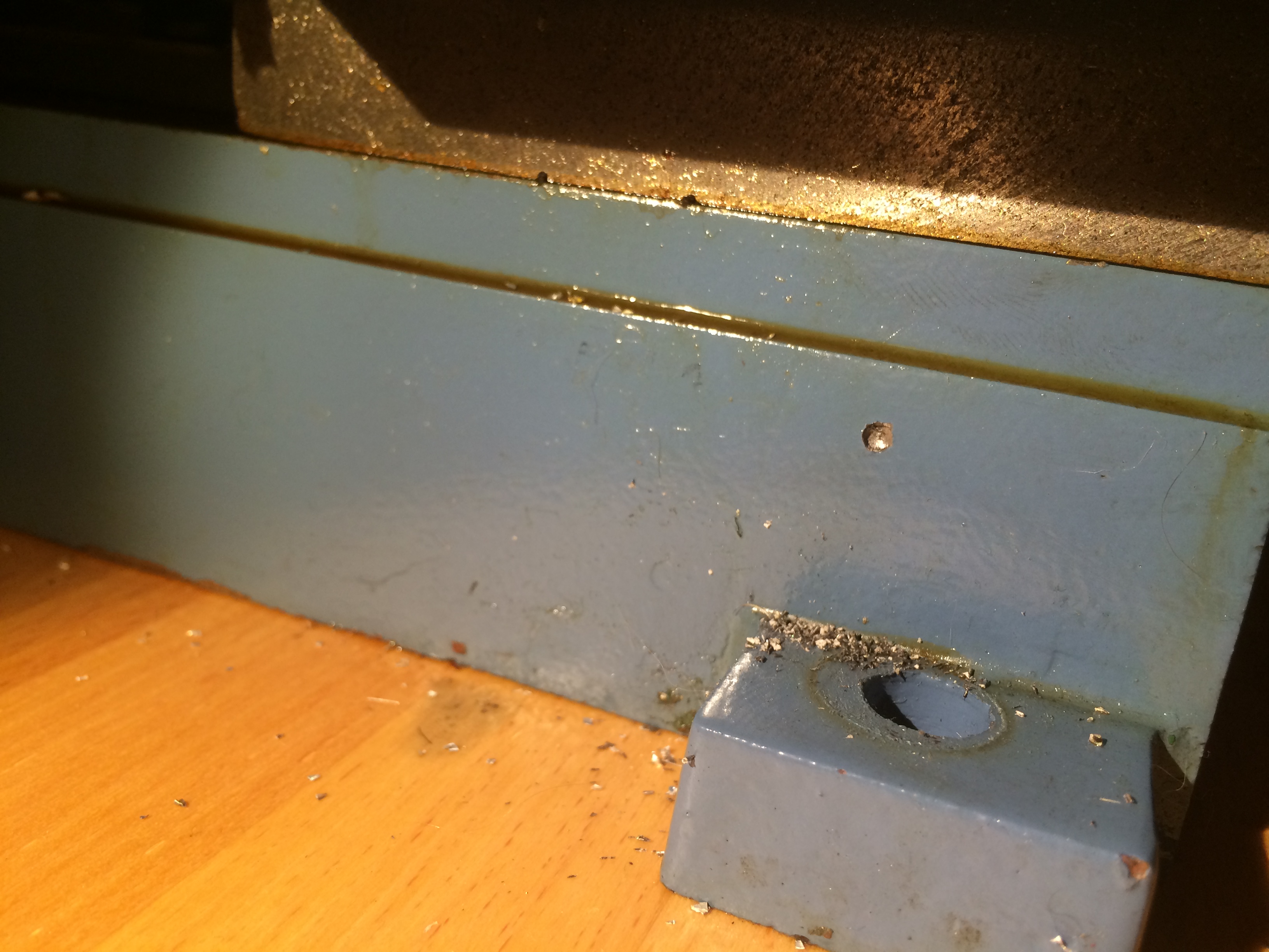
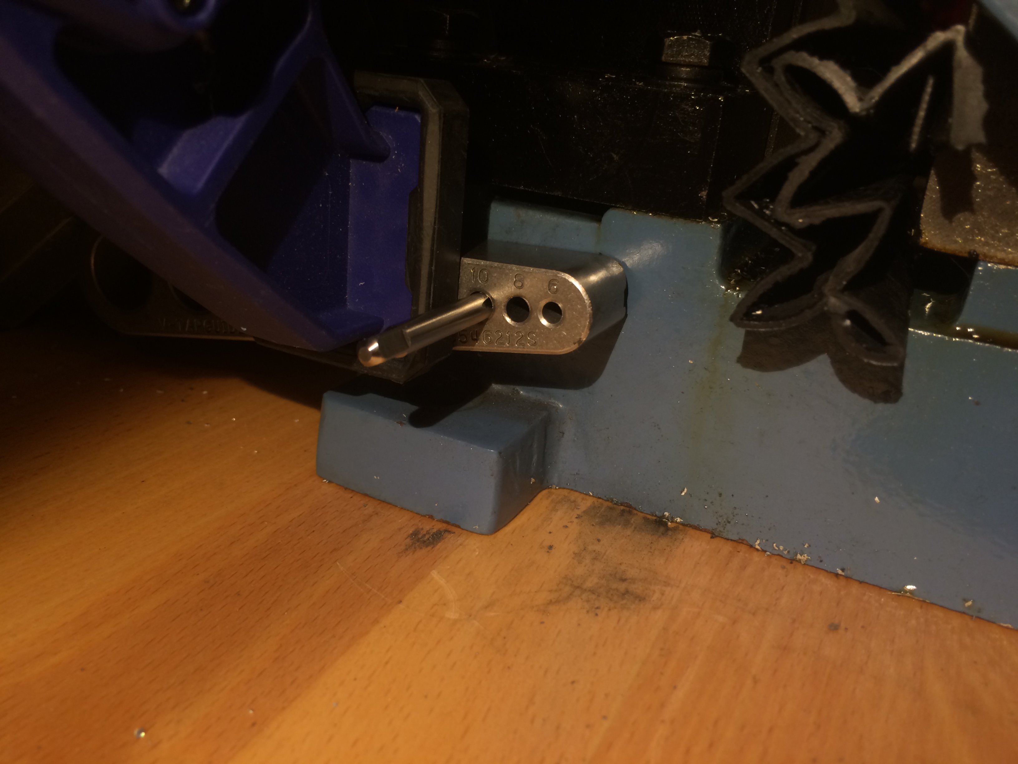
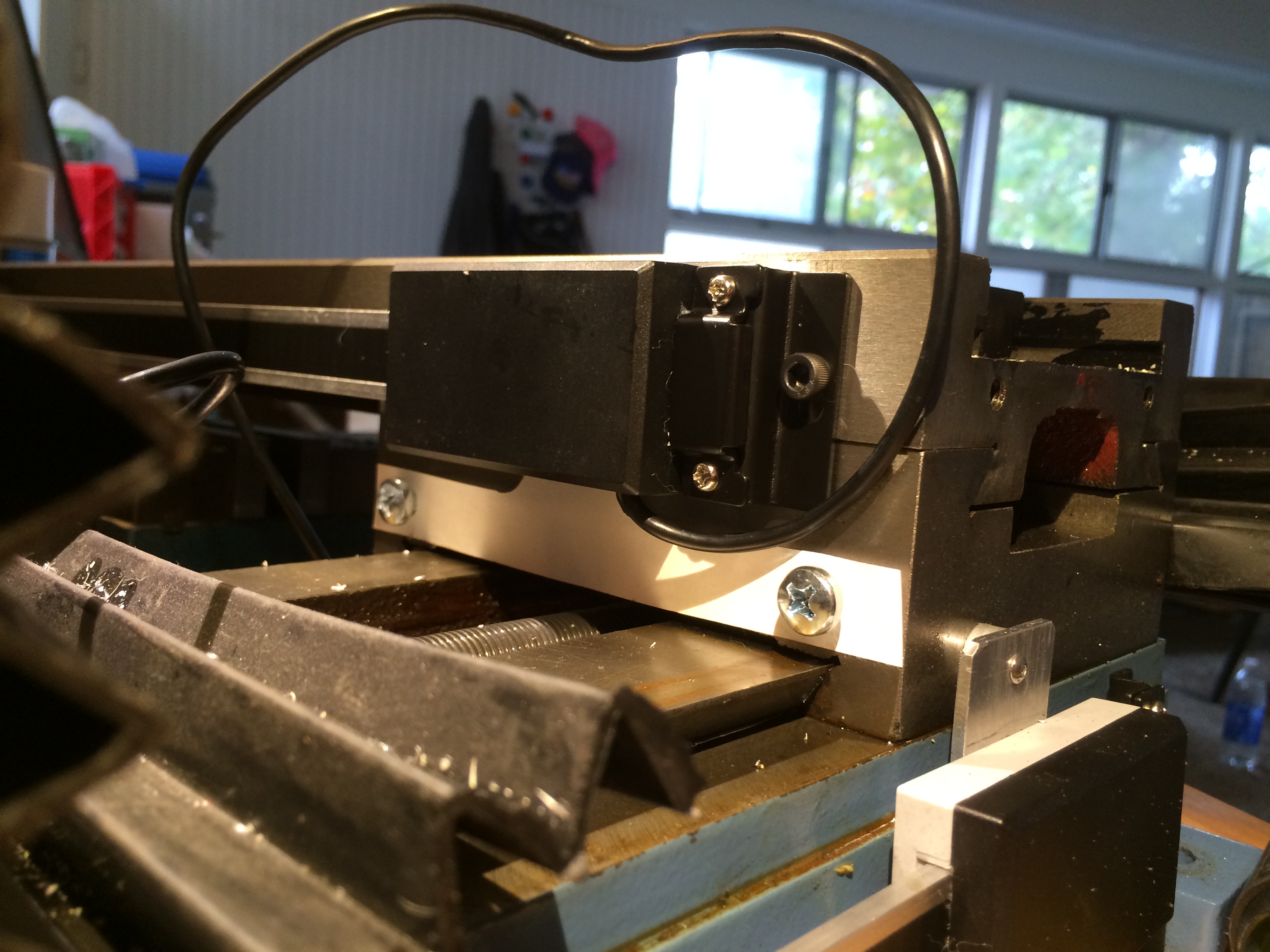
For the y-axis I used the 8″ travel DRO version. Here the scale is fixed to the base and the read head follows the saddle. I mounted the scale about 1.25″ back from the front of the base using 10-32 hardware (fits nicely in the existing slots on the scale.) The cast iron base drills and taps pretty easily. I recommend a drill and tap guide be used here as matching the base’s 5° draft is tricky without one.
Mounting the scale directly to the base means the read head and saddle are no loner parallel. To account for this the bracket that connects the read head to the saddle has a matching 5° bend. The bracket is made from a scrap sheet of 0.090″ 5052 aluminum sheet. The distance between mounting holes is 20mm, all the others dimensions were just roughed in by hand. I clamped the bracket in a vise and use a crescent wrench and protractor to set the angle.
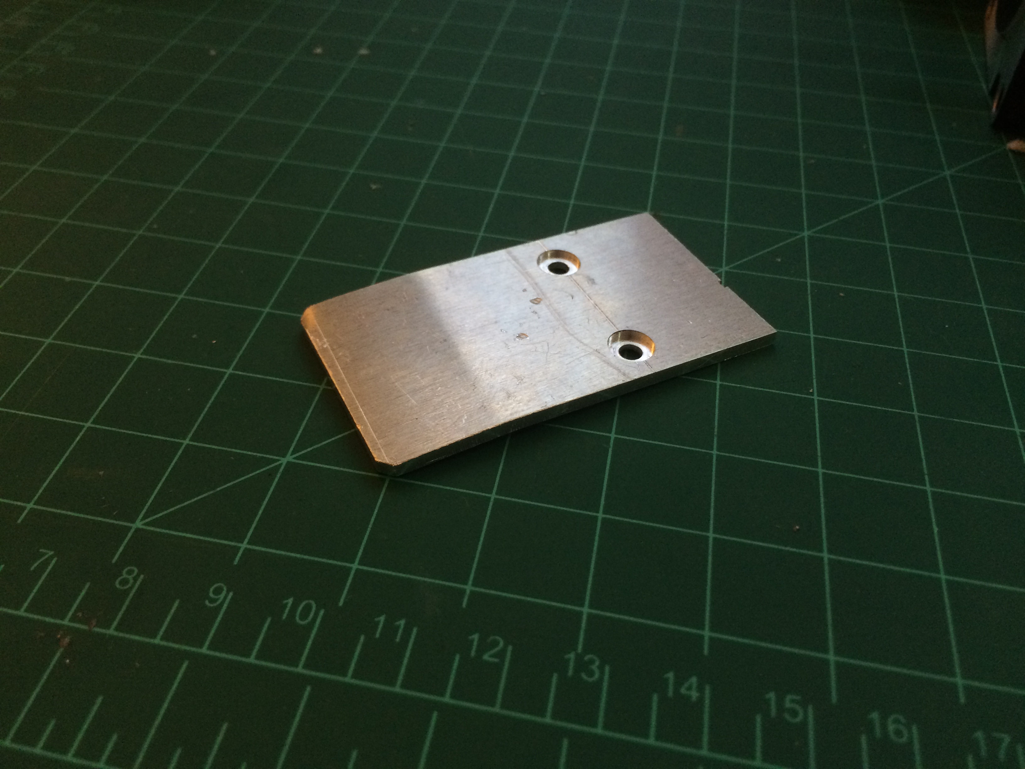
The holes for the read head hardware received a slight counterbore as the included screws are pretty short (with good cause, a too long screw will dig into the scale and damage it.)
A single 4-40 screw and spacer attach the bracket to the saddle. I match drilled the hole in the saddle to the hole in the bracket as this was easier than trying to measure and mark the saddle while it was in place. You’ll want to make sure you mount the rear head far enough back on the saddle that the read head does not hard stop against the scale when the saddle is all the way forward.

X-axis
The procedure for the x-axis was similar to the y-axis, mount the scale, then design a bracket to mount the read head to the mill. I decided to mount the DRO scale on the rear of the table to reduce clutter near the front of the machine. Here it seemed easier to fix the read head to the saddle and let the scale travel with the table.
I started by mounting the 12″ DRO scale on the backside of the table. The scale needs to be mounted low enough that nothing sliding across the table will hit any part of the scale. Again, 10-32 hardware fixes the scale to the table.
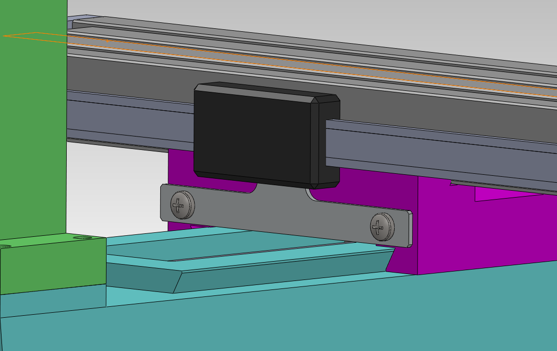
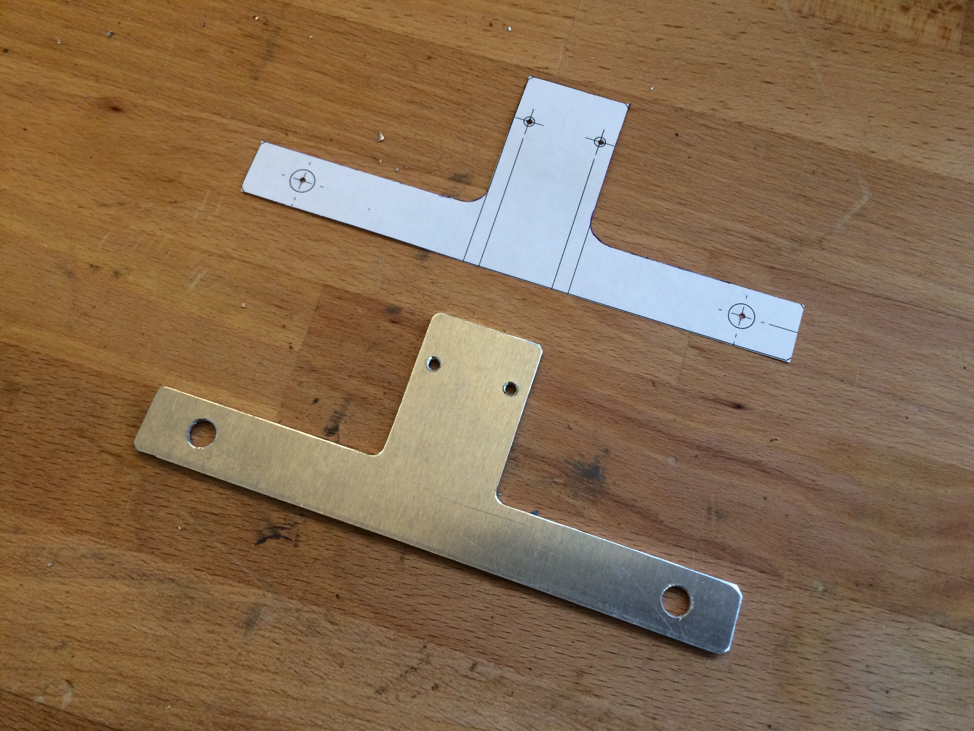
Re-purposing the way cover mount screws kept me from needing to drill and tap into the rear of the saddle. I took some measurements of the read head position relative to the saddle, put that into CAD, and drew up a bracket.
A quick check of the bracket fitment in paper.

Checking for fit with a paper version proved it’s value, as one of my measurements for the way cover screw holes was off by ~1mm, if I had made the bracket in aluminum first without checking I would have had to modify the bracket I had just made.
More scrap aluminum (same .090″ 5052 as before)

Free handing the outline

 Fitted to the read head. I needed a 2mm spacer between the bracket and the saddle. A double stack of M6 washers did the trick.
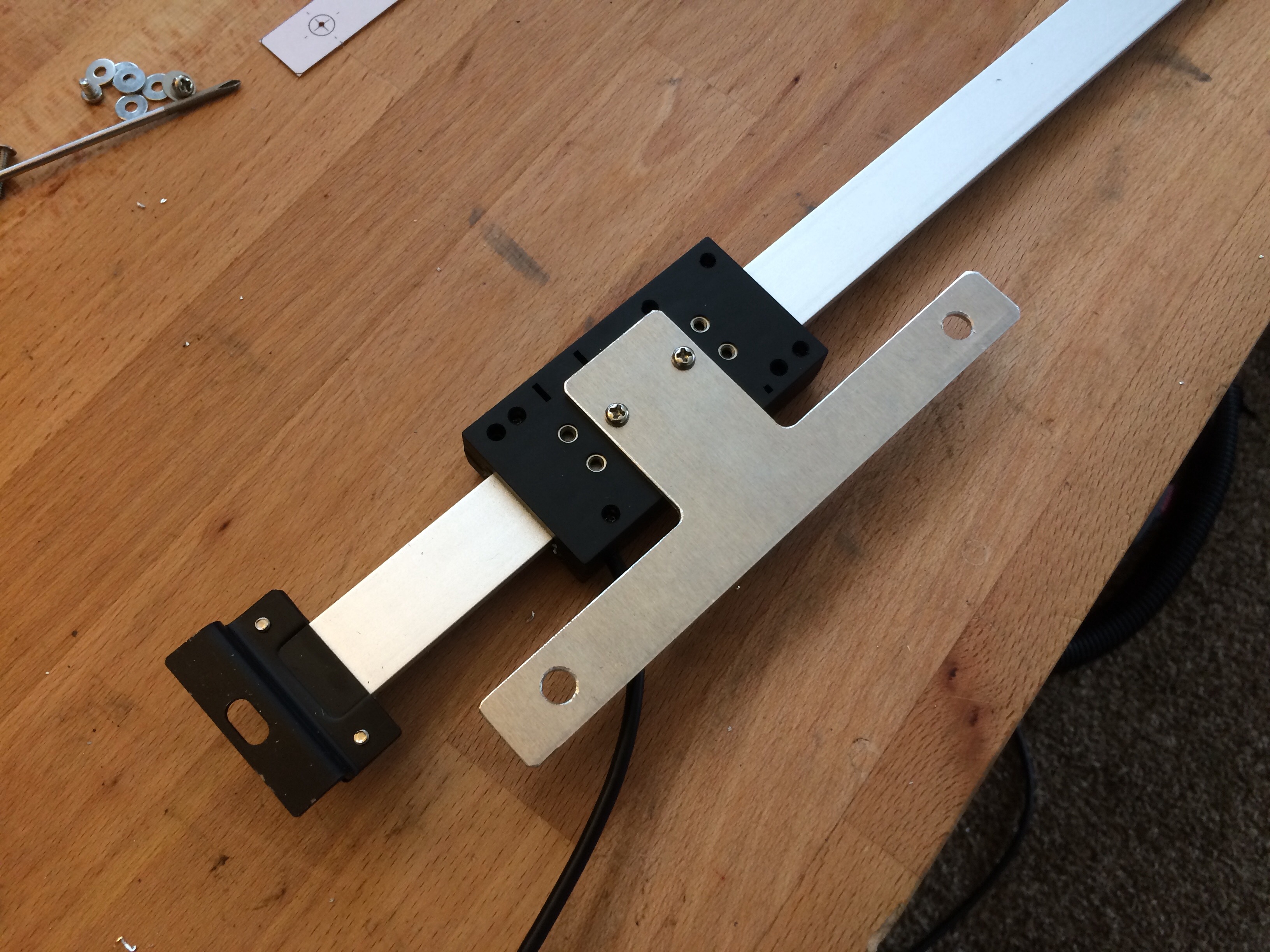
Here you can see how I was able to keep the existing way cover mount method by getting longer M6x12mm screws to replace the existing ones. The DRO bracket and spacers get sandwiched between the way cover and saddle.

For now I am just installing scales on the x and y axes. I’m going to try some work arounds to get the Z height dialed in, but I may end up putting a scale on that one too.
