Since I decided to debut the mini molder at Maker Faire bay area a custom mold was in order. One of the more iconic images for Maker Faire is the Makey robot figure. It has roughly the correct proportions for a mold-a-rama figure, and a simple enough profile for my basic CNC abilities. I found an image of a pin sold in the maker shed.

I traced the above image in solidworks and created a model of the figure.

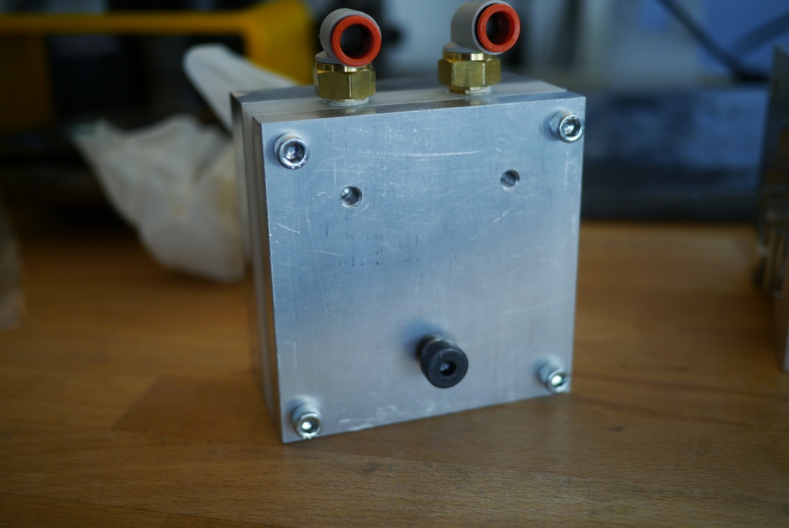
The base on the bottom is partly for stability, but also a result of the liquid plastic entry and exit ports. Those ports are not quiet aligned with the legs of the robot, so the flat base ensures the mold cavity is always around the two liquid plastic ports.
Once the figure was modeled I created mold halves using the cavity feature in solidworks and added various holes for screws.

In most injection molding dies, water channels are used to route chilled water around the mold, this helps cool the part faster enabling a faster cycle time. Mold-a-rama dies had a water jacket cast into the back side of every mold die. The mold cylinder mounting plate on the back doubled as a block off for the water jacket.
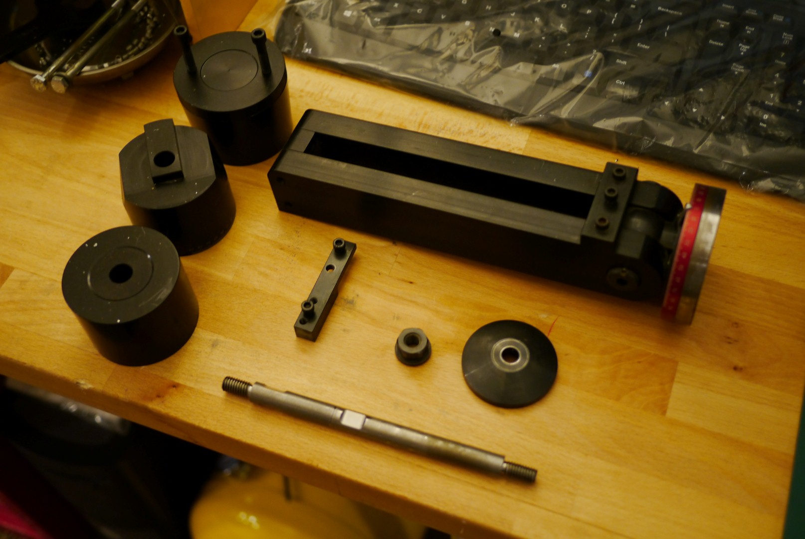
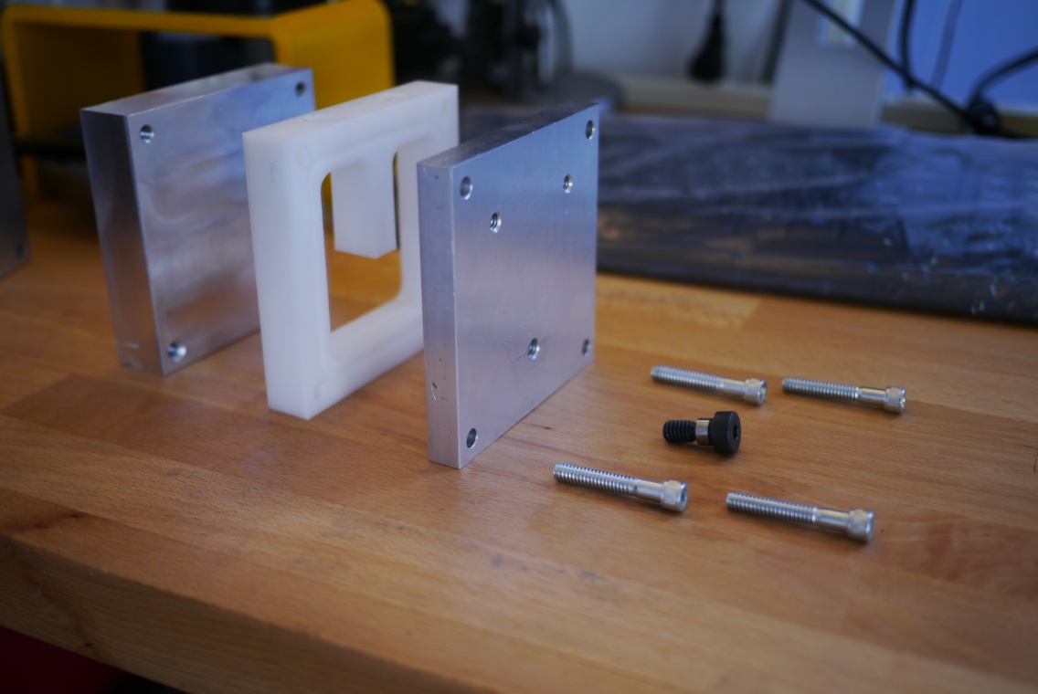
The mold dies I designed consist of several parts:
- Mold face with part cavity
- Water channel spacer plate
- Rear mount plate
I decided to make the mold die in multiple parts for a few reason. The first is that more of the mold is reusable should I want to make a new mold design. If I had cut the channel for the water directly in the back of the mold, I would have to cut that same feature in the back of every new mold as well. Making a separate water channel spacer means fewer setups on the CNC mill. The second is that cutting a water jacket in the back of an aluminum mold would take an enormous amount of time on my little CNC mill, the much faster material removal rate of delrin made this an easy decision.
What follows is a mostly complete step-by-step of the machining process for the mold spacers.
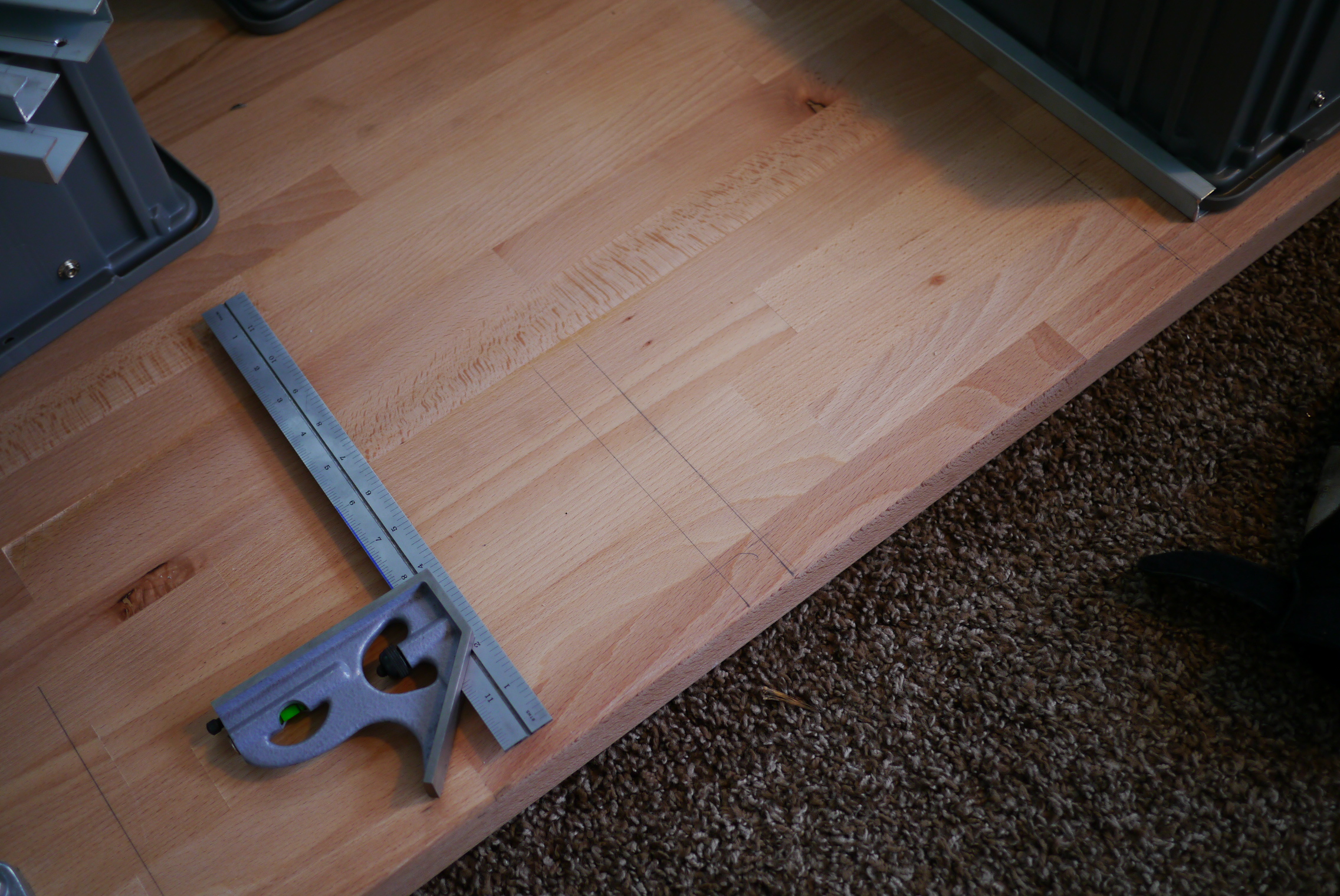
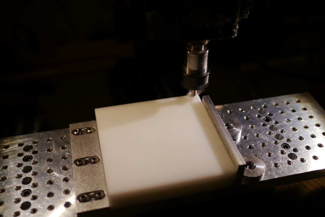
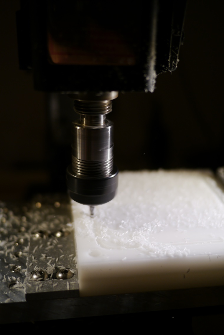
After rough cutting the delrin stock and squaring the sides, it is tightened down to the tool plate in my mill.

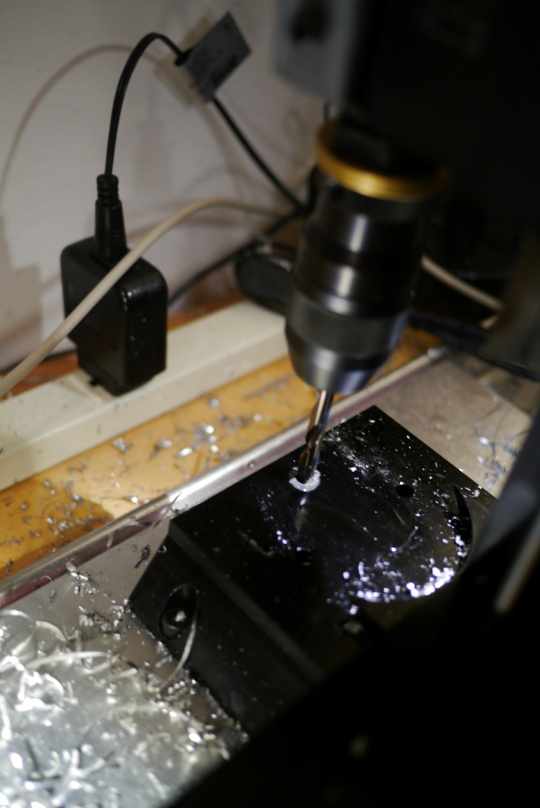
Setting the tool height so my mill knows where the top of the stock is relative to the tip of the cutter (center drill in this case)

Drilling clearance holes for the 1/4-20 screws that hold all the mold sandwich together.
1/8″ 2 flute carbide end mill creating the o-ring groove.
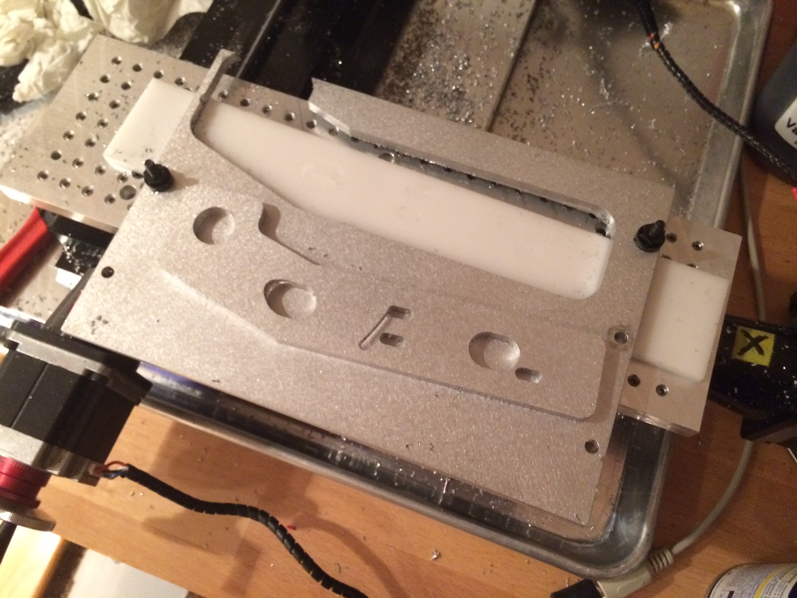
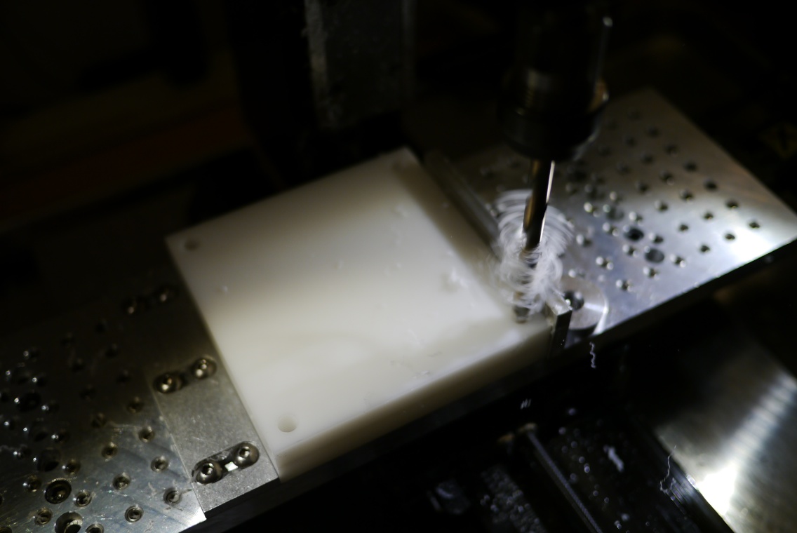
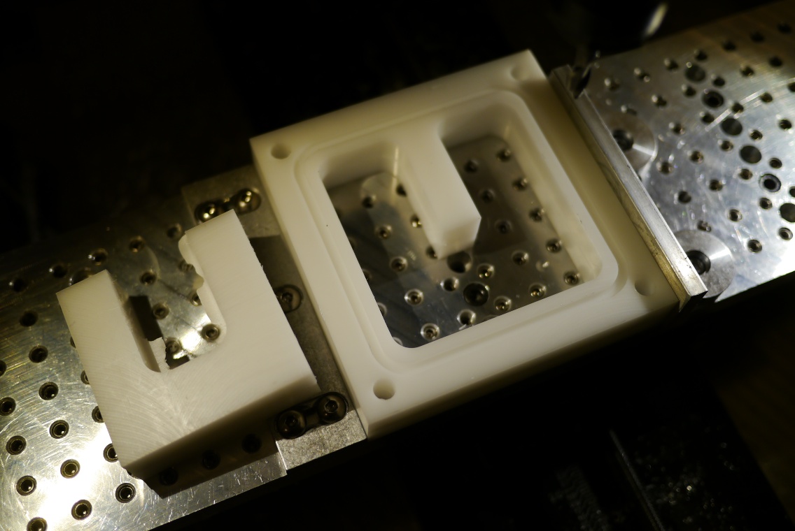
This center u-shaped section is where the water flows into and out of the mold cooling cavity. The entire center section needs to be cut out. Since I don’t want to cut into my tool plate, I cut the slot to half-depth, then flipped the part over and cut it again. Flipping parts is always tricky, as any small misalignment will show up were the two cuts meet.
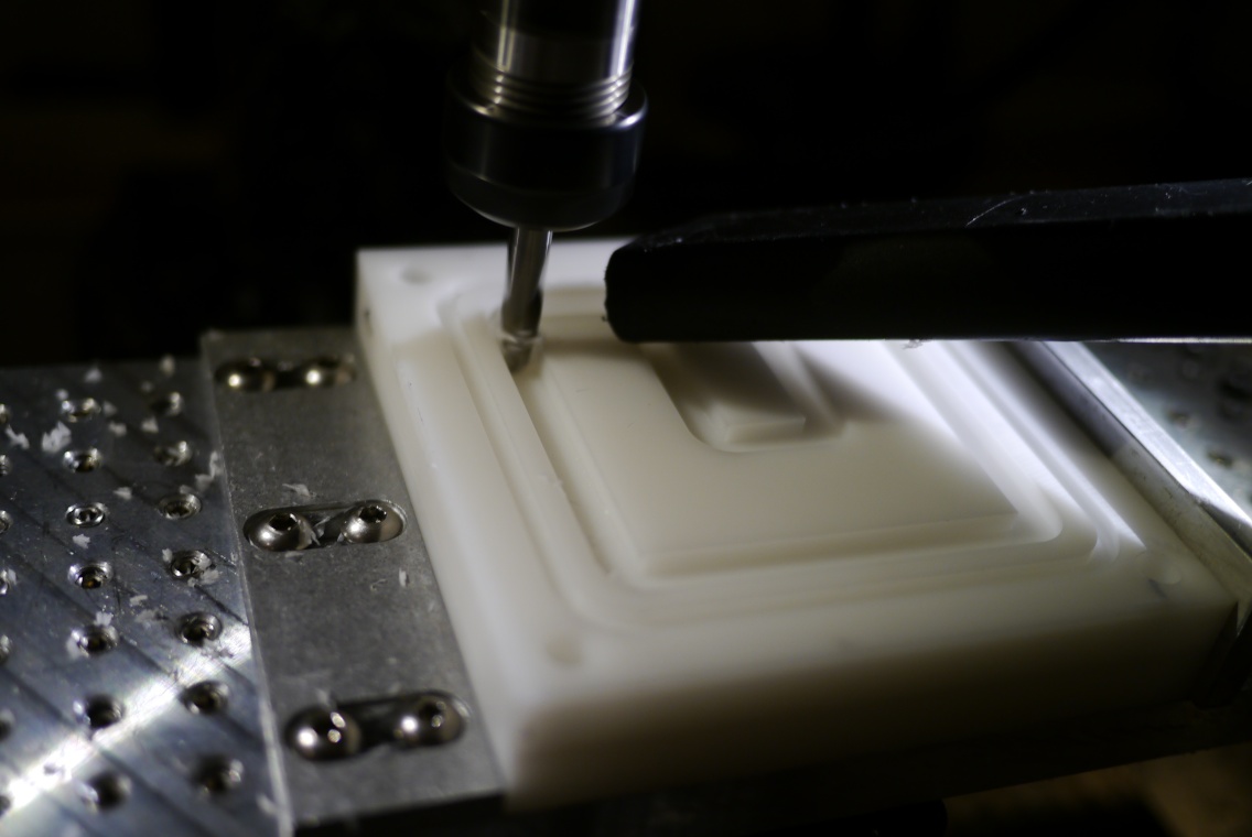
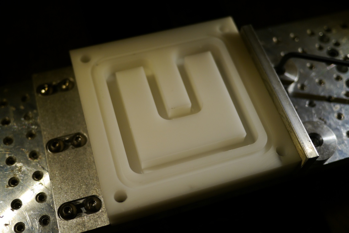
In the first part I made, I removed all the material bit by bit (machinists call this pocketing), this took a long time. In the second part I used a 1/4″ 2 flute carbide end mill to cut a half depth slot around the piece of delrin that was to be removed. Flipping the part over, re-cutting the same path and the whole center section comes out in one piece.
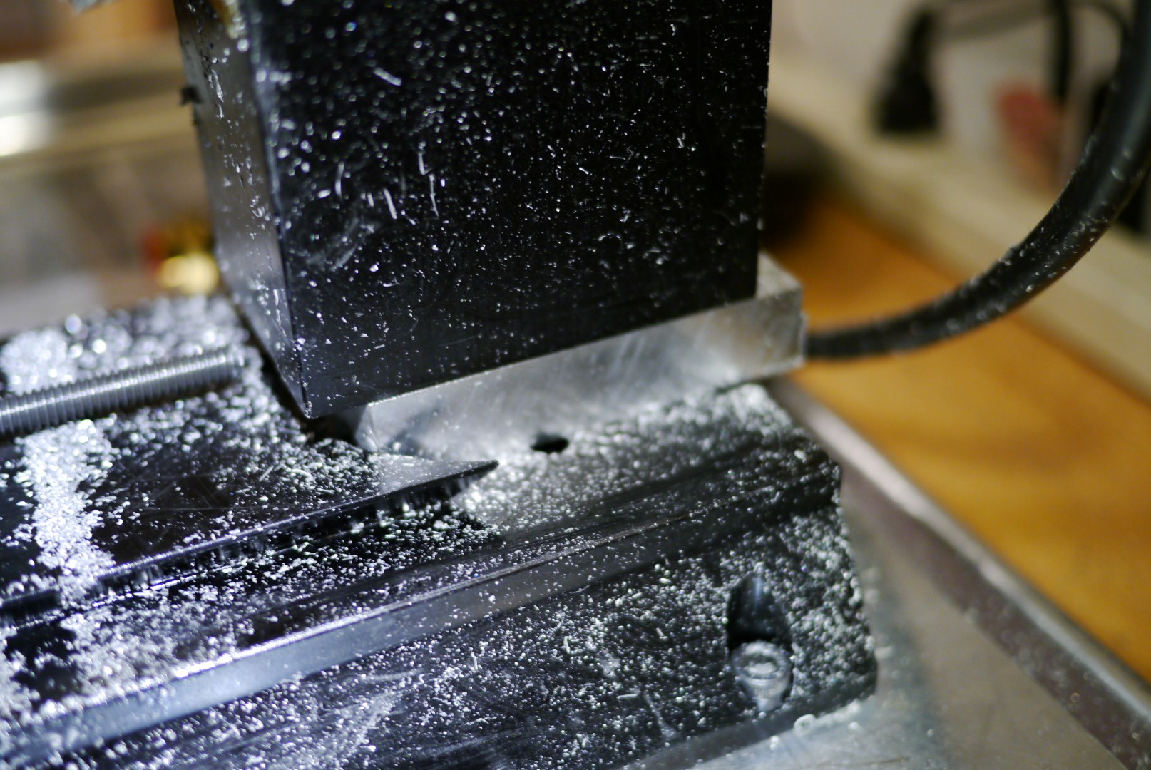
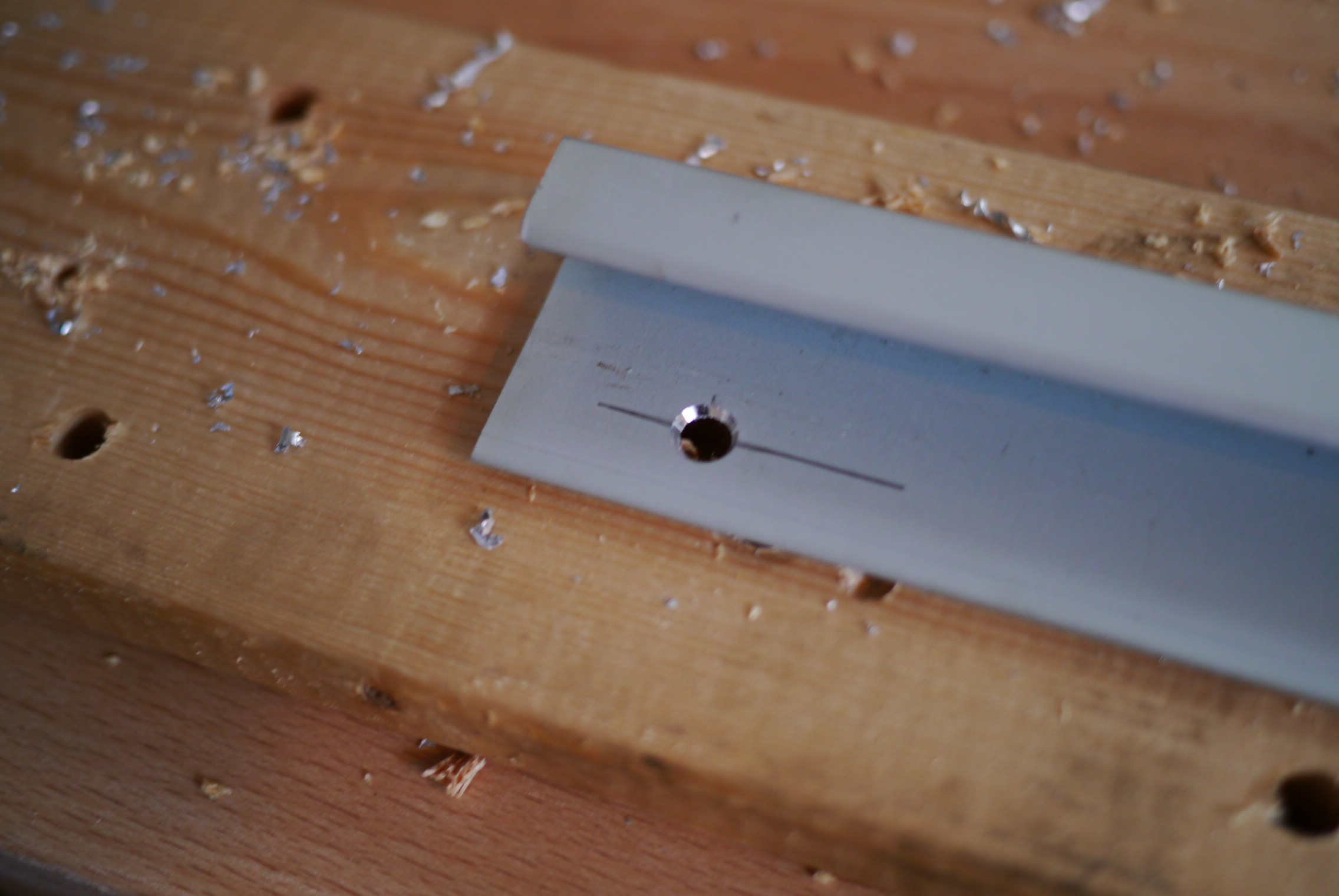
The last step on the spacer plate is to drill and tap the NPT threads for the pipe fittings. The drill bit needed to drill this hole was too long to fit in my mill, with its limited z-travel. So I milled out the hole using a 3/16″ end mill.


Taping large threads like 3/8 NPT take a decent amount of torque, so your part should be firmly mounted. I sandwiched the spacer plate between two backer plates, put them in my screwless vise, and then clamped the vise to my shop table.

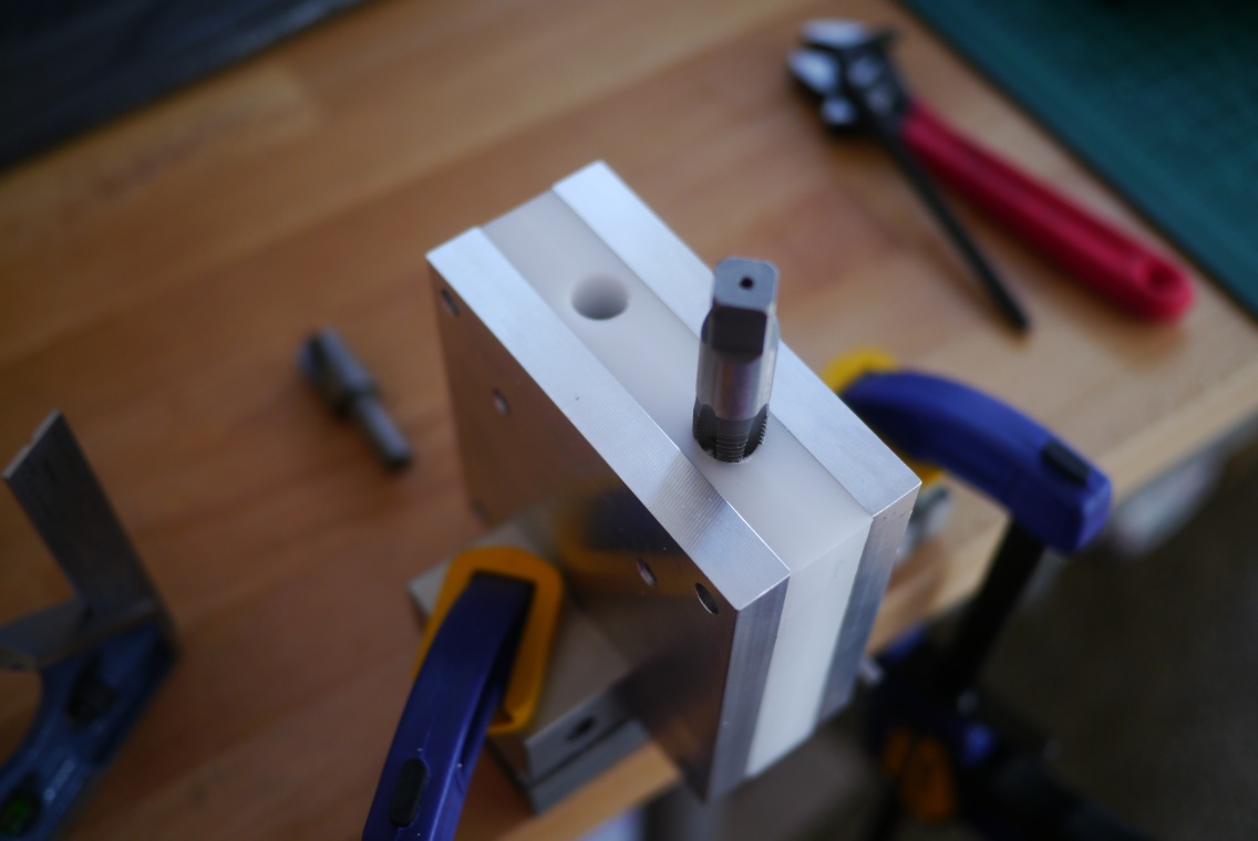
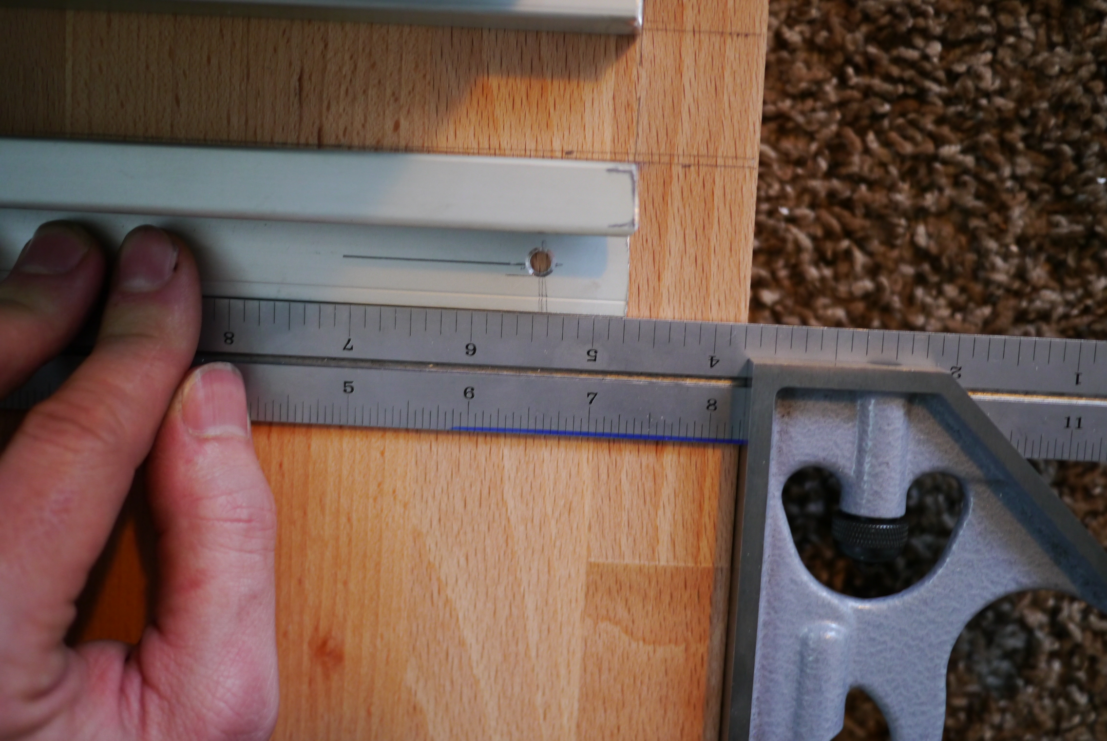
Getting a straight start on your tap can be pretty tough without a tap guide, or performing the operation in a mill. I used a small square to align the tap, going slowly and re-checking after each turn.

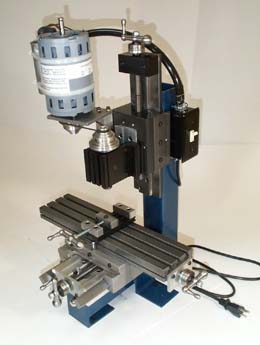
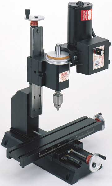
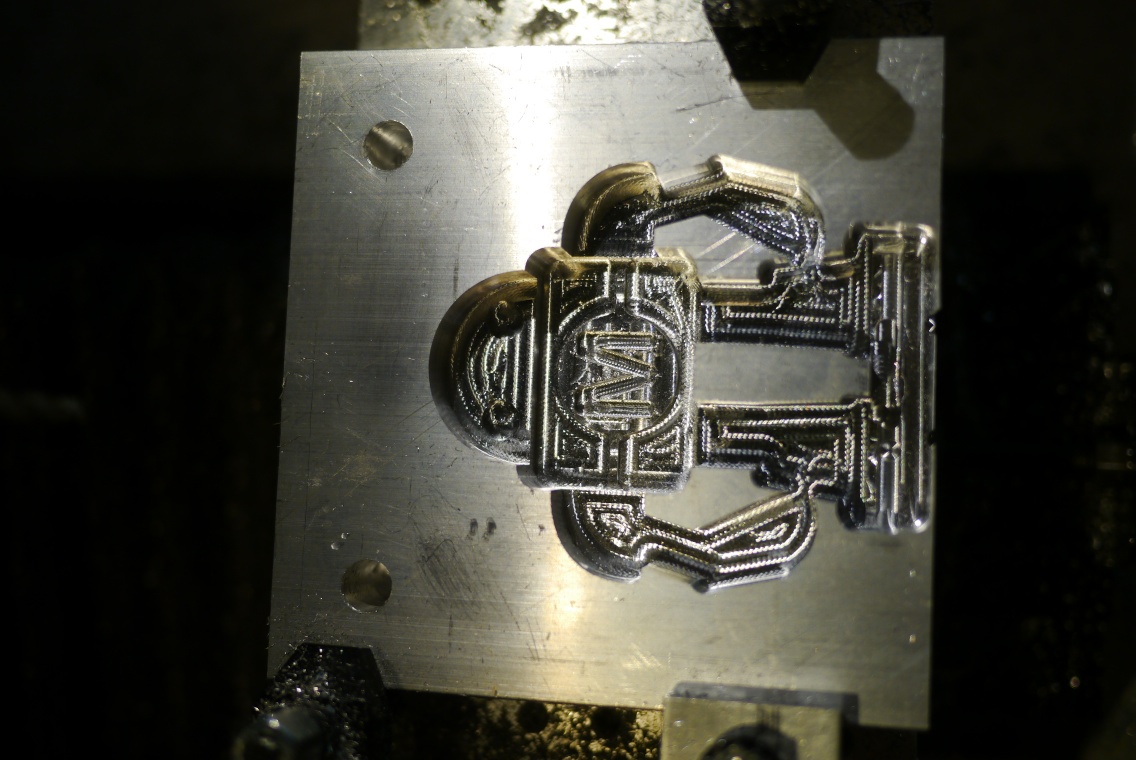
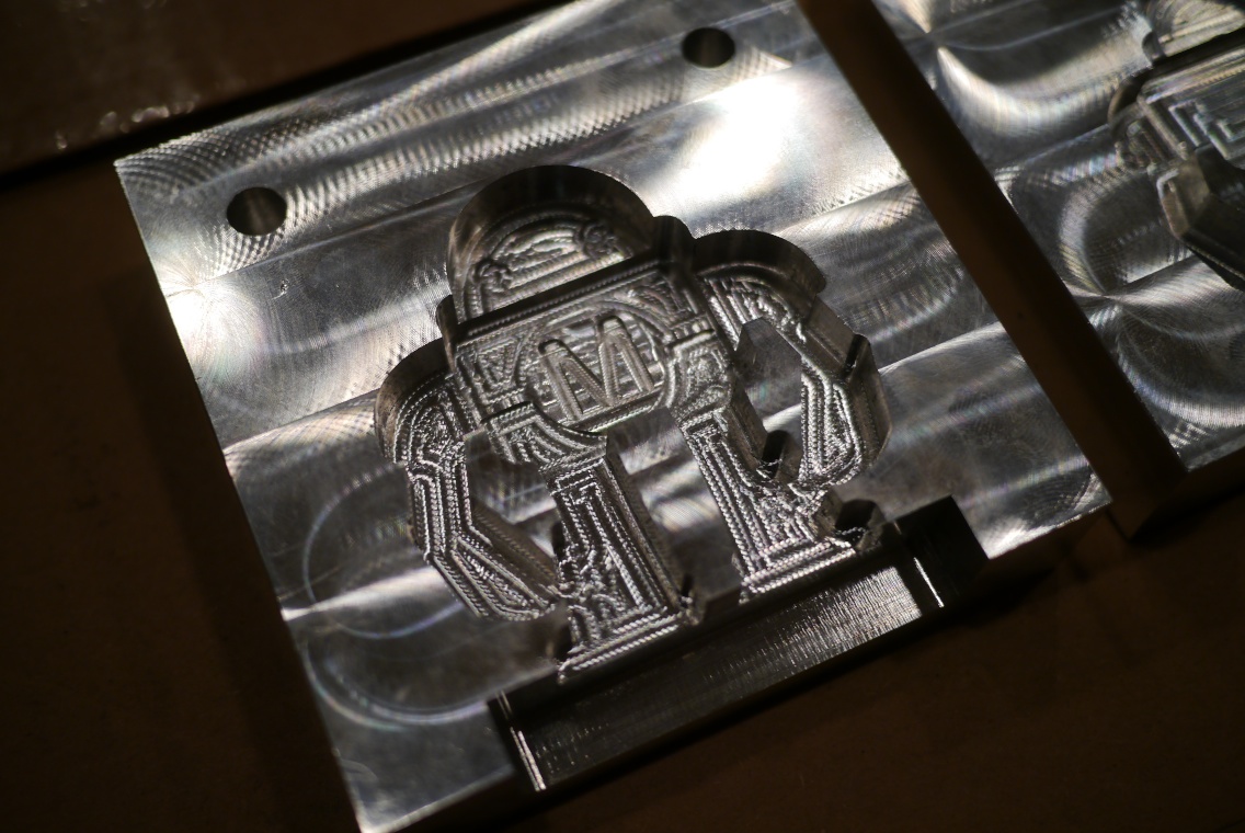
The mold faces started life as a piece of 4″x1″x12″ 6061 aluminum. Like the spacer plate before, they were cut to rough size on a band saw and then squared up with a fly cutter on my sherline mill. I don’t have as many pictures of the milling process, but I did take a time lapse video.


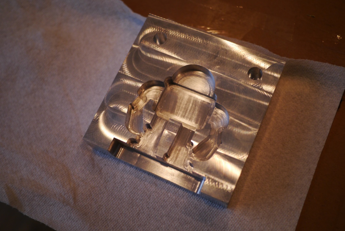
To remove the tooling marks left by the mill cutters, I used 400 grit wet or dry sand paper and some free labor (thanks Ashley!) It was time-consuming, but gave me a greater appreciation for what goes into achieving a mirror like finish on all the plastic products I see.
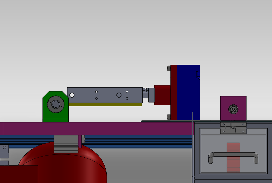
Exploded view of one of the mold dies (minus o-rings).
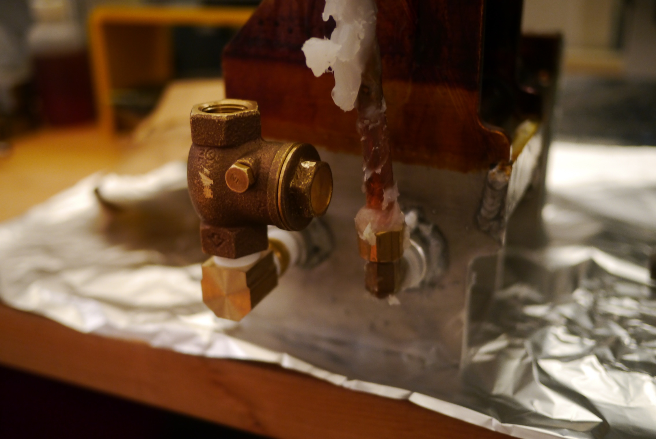
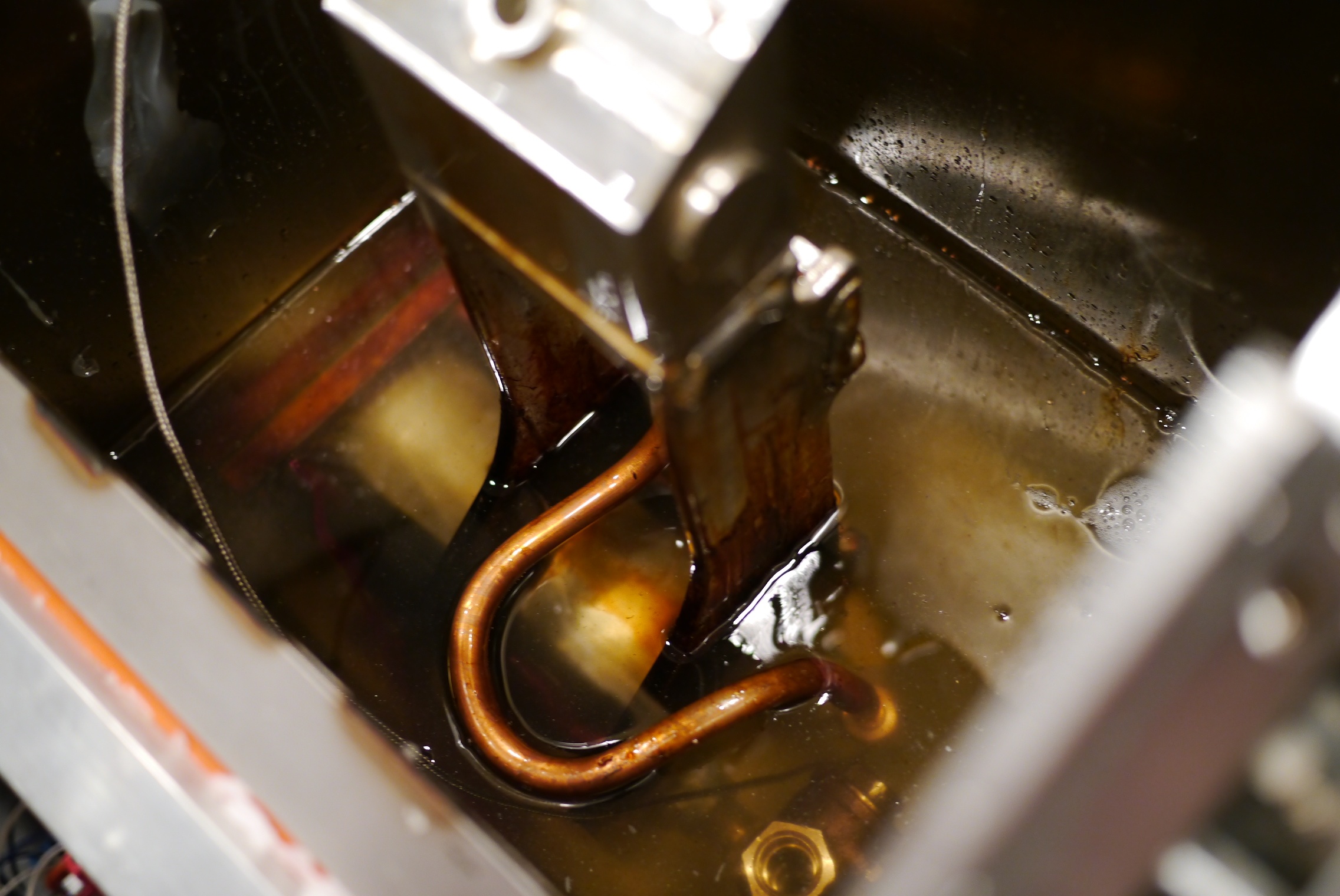
Spacer with its two o-rings. I used plumbers faucet grease as an o-ring lubricant as it was what I had on hand.

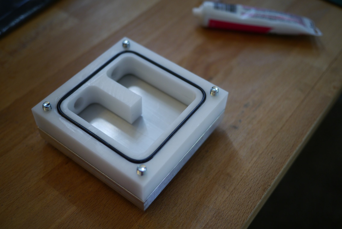
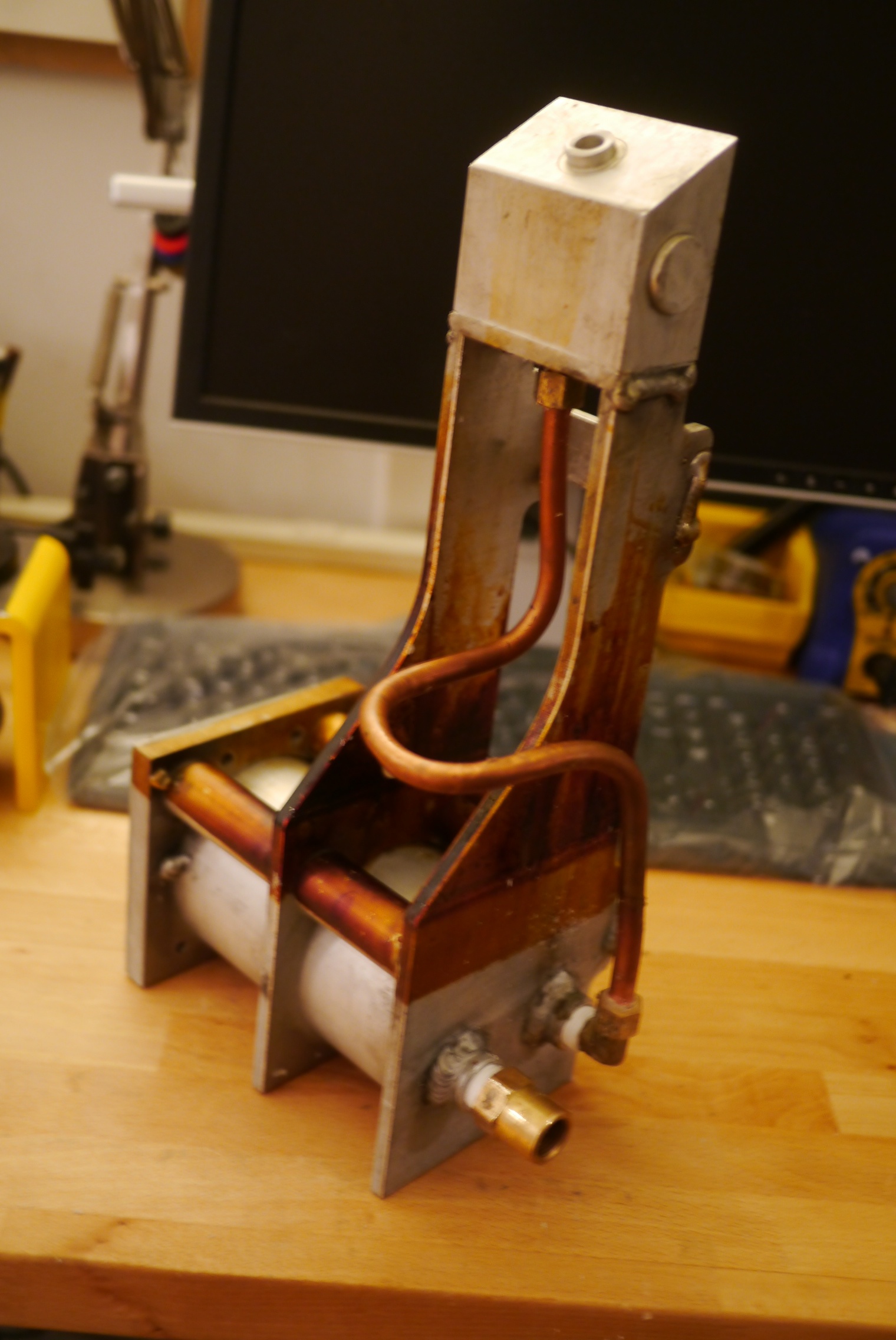
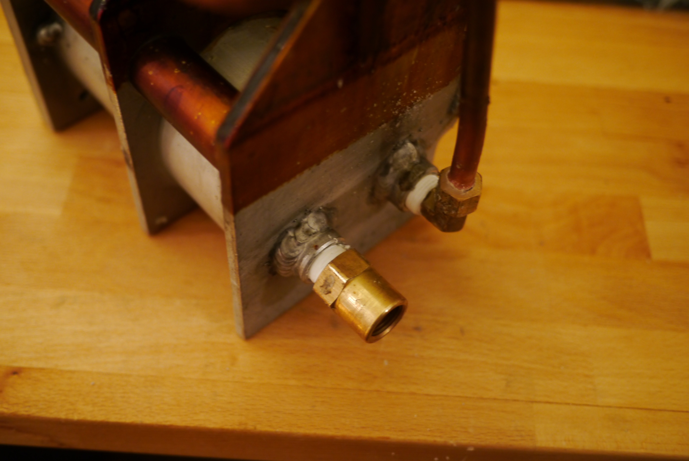
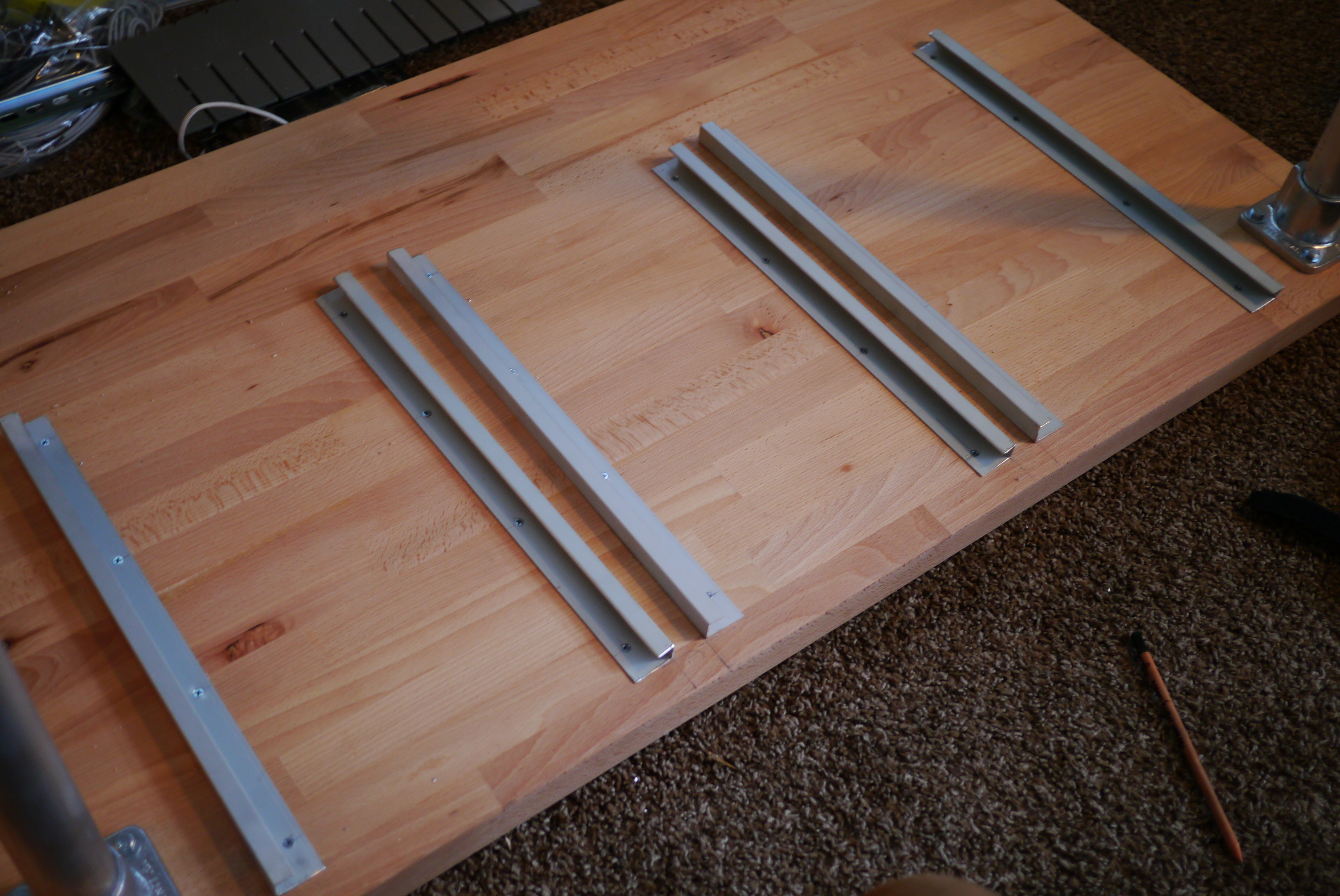
Assembled with pipe fittings installed.