
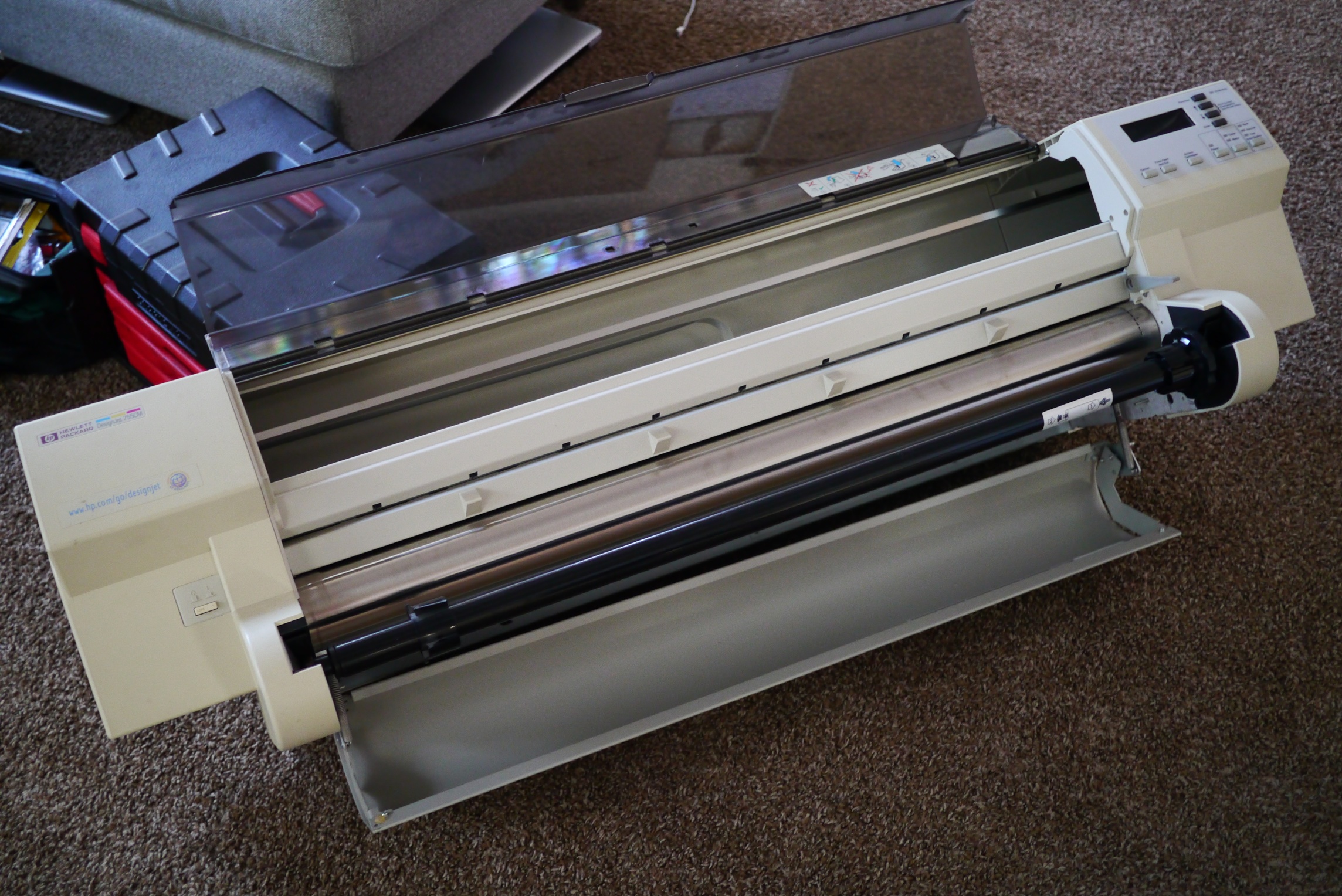
A friend of mine found an old HP plotter from the mid 90’s on the side of the road. Knowing I was into electromechanical objects he asked if he should pick it up for me, and of course I said yes. We initially though about repairing it (its drive belt had desintigrated and it needed new ink), but realized that even after fixing it it would have little resale value. We decided to take it apart and harvest it for parts, while along the way looking for interesting mechanisms and design features.
Printers are chock full of useful parts like motors, linear slides, encoders, and switches. In fact a very small crude CNC router could be made from the parts of two inkjet printers.
First impression based on getting it out of the car: this thing is heavy and built like a tank; the specification sheet says 95 lbs.
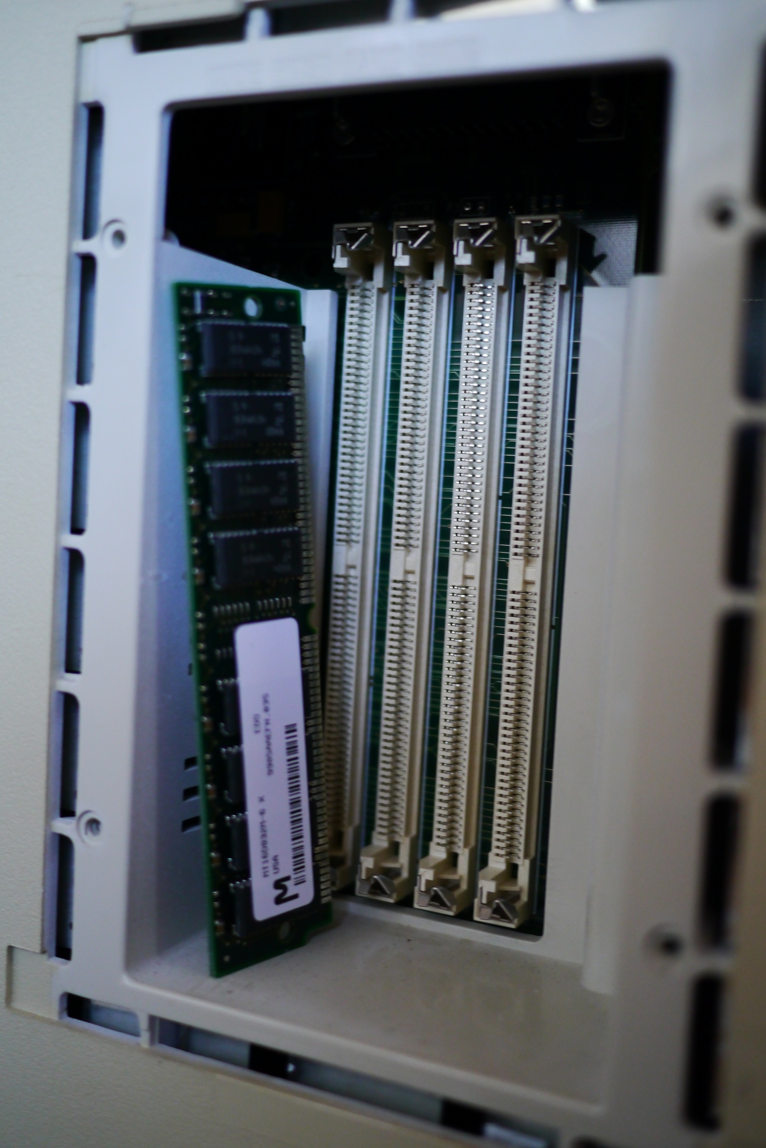
Opening an access door reveals a few MB’s of RAM on standard SIMM cards.
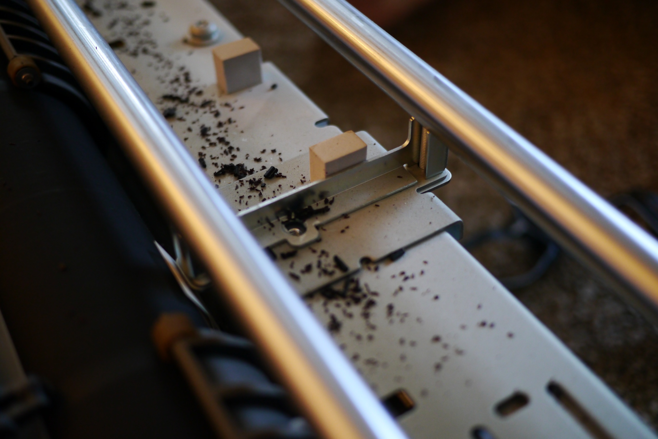
Removing more covers, and now we can see the linear encoder for plotter’s print head. This encoder sends position feedback to the plotter; once homed, the print head’s exact position along it’s travel is known. Barely perceptible scribed lines are in the lower clear portion. The black square in the center of the picture with white text is the read head.
The silver looking strip is actually a stainless band that is pulled taught by a tensioner at the end. The considerable tension is needed as any sag in the encoder strip would lead to position errors of the print head and messed up prints.

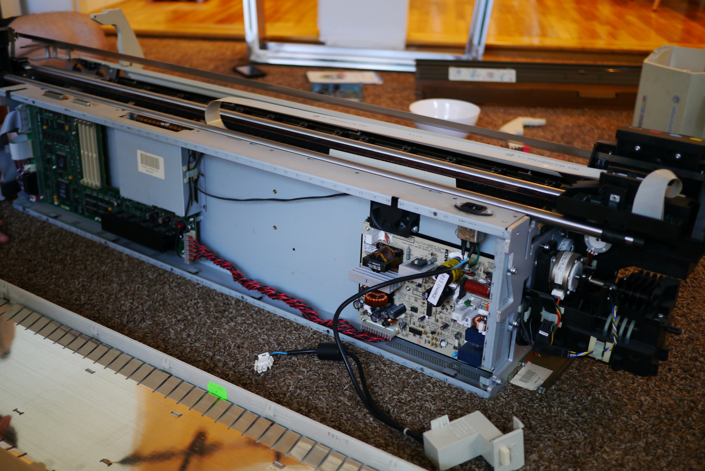
A view of the back, main control board on the left, power supply on the right.
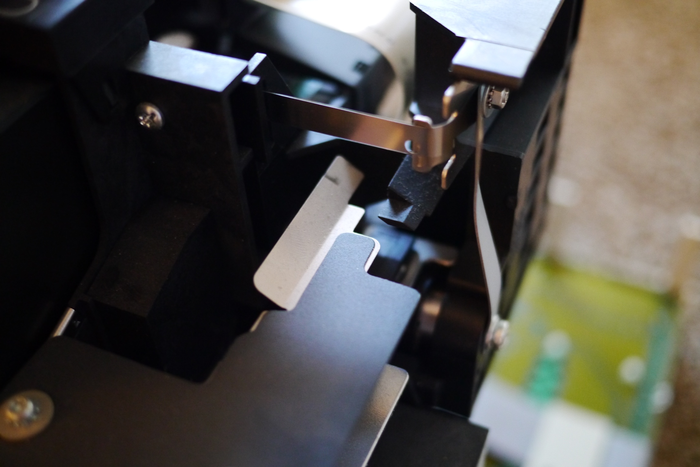
The round circle with a bevel is the paper cutting blade. Since paper for plotters comes in a continuous rolls, a blade is necessary to cut each print job to length.
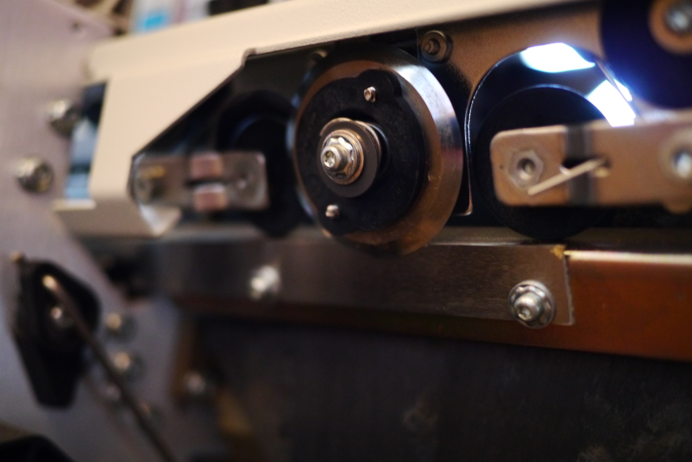
This part has a pretty ingenuous mechanism to move it across the printer. Rather than having another motor and belt move the cutter, it hitches a ride on the print head, thanks to a one way catch.

The plastic ramp on the right is part of the print head. The sheet metal part in the center is attached to the circular paper cutter carriage. When the paper needs to be cut the print head moves all the way to the left, the sheet metal part goes over the ramp on the print head and gets caught. The print head then moves to the right with the paper cutter in tow. Once the cut is finished, the print head move to the left pushing the cutter back to it’s start position.
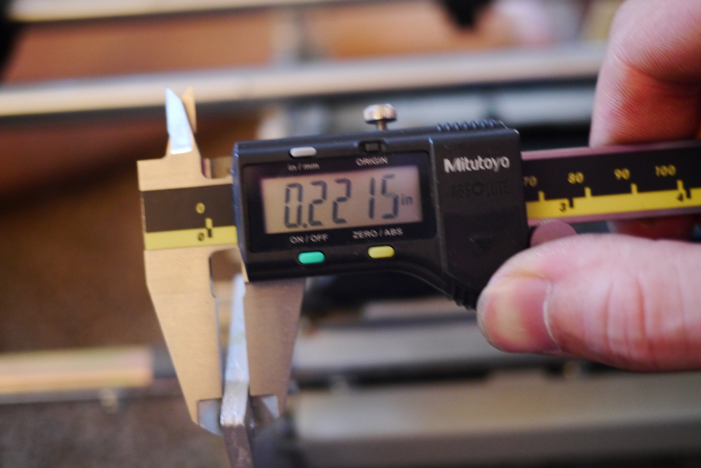
Stripping it further, the liner rails the print head rides on can be seen. Also drive belt remains.
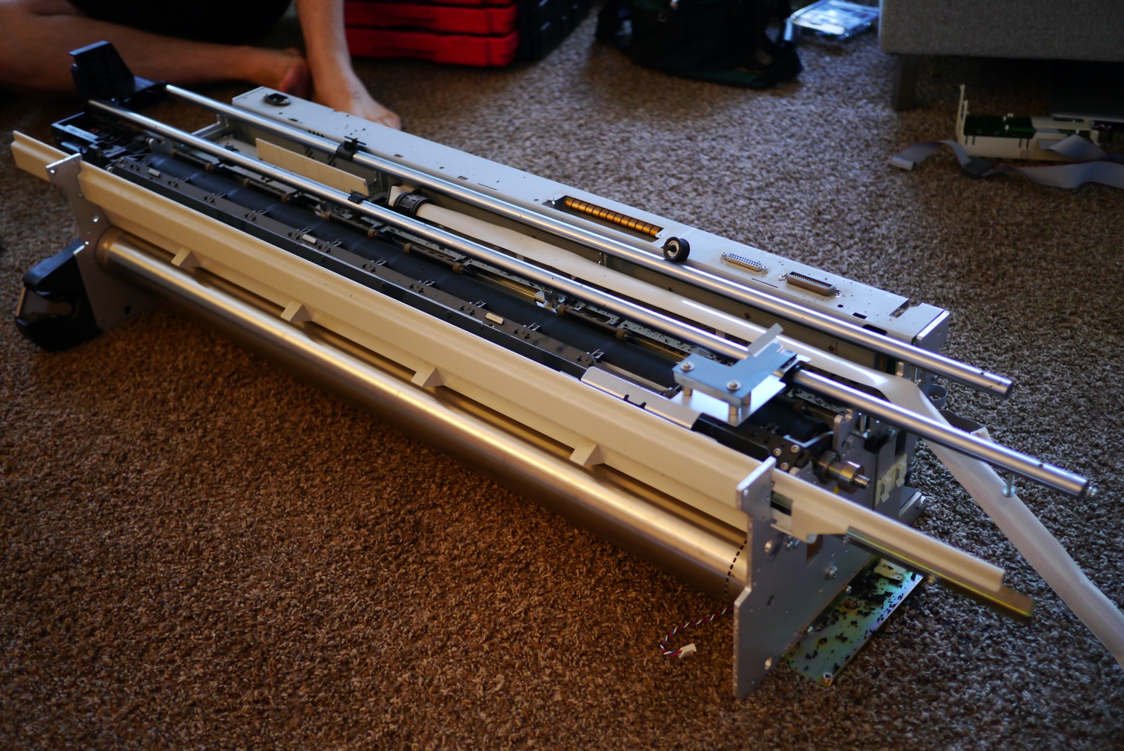
These were solid steel and very stiff.
The part below is a little vacuum pump that sucks excess drops of ink from the printer head when it is at it’s home position.
The vacuum head pops up thanks to a little stepper motor, and has wipers to further clean the print head.
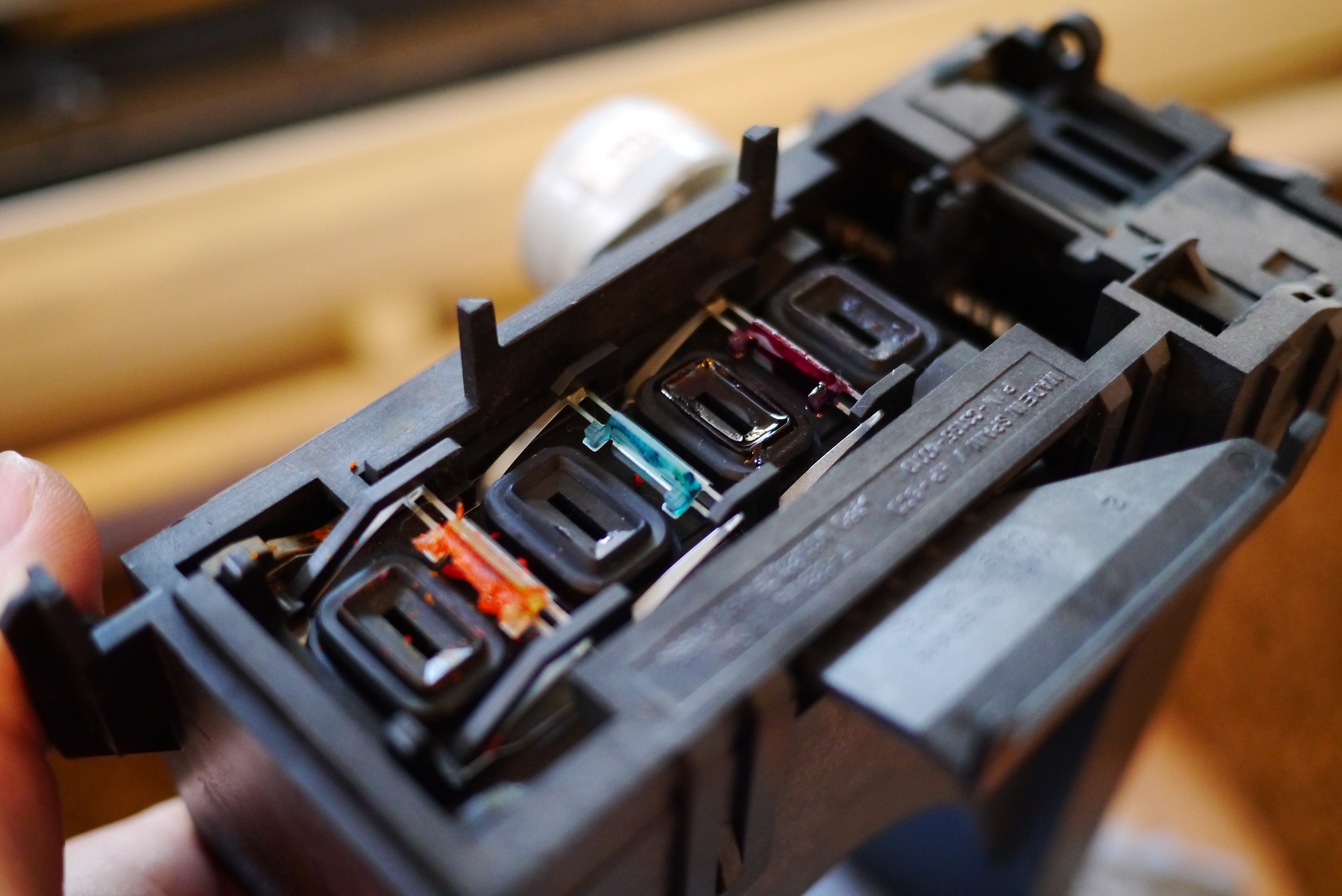
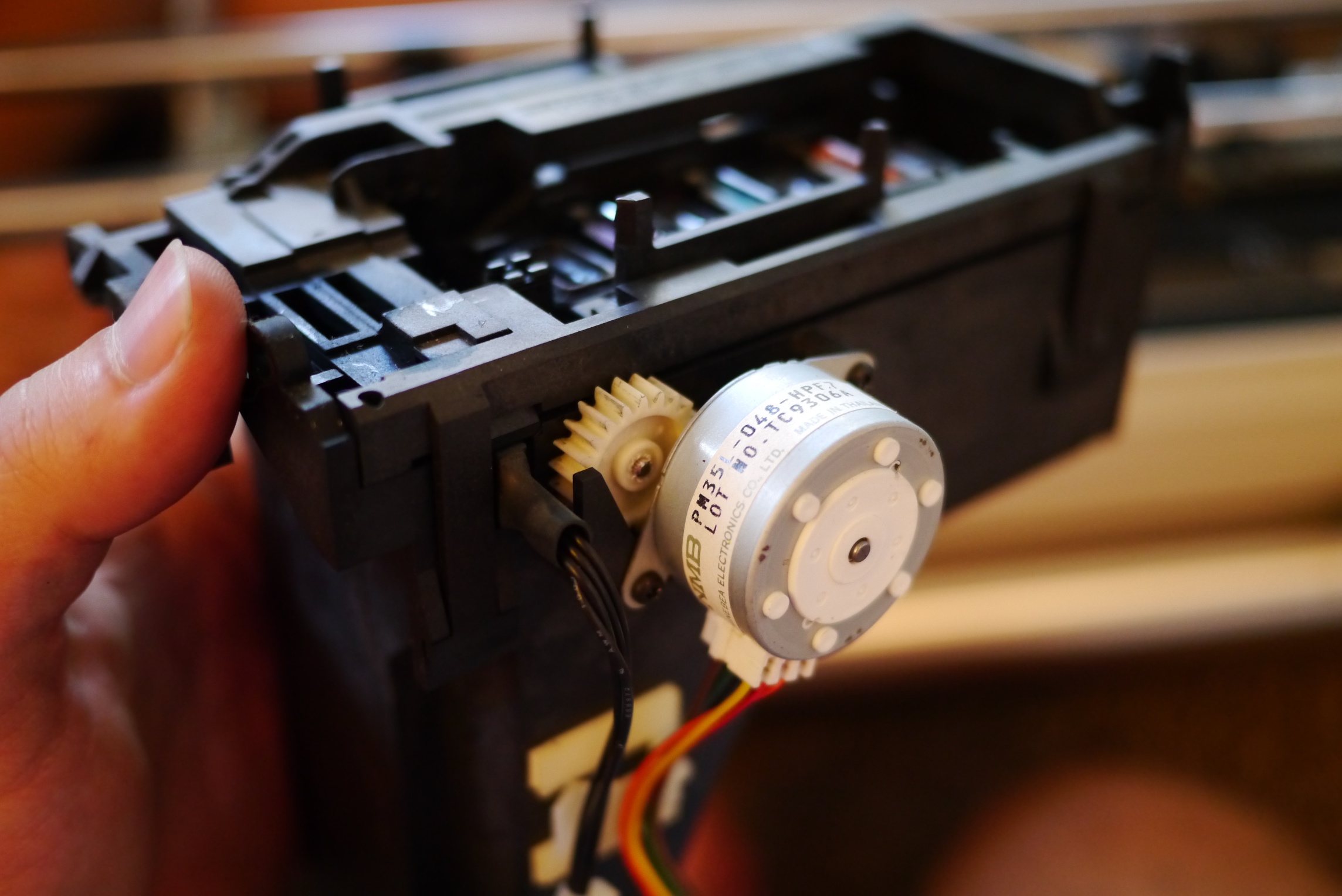
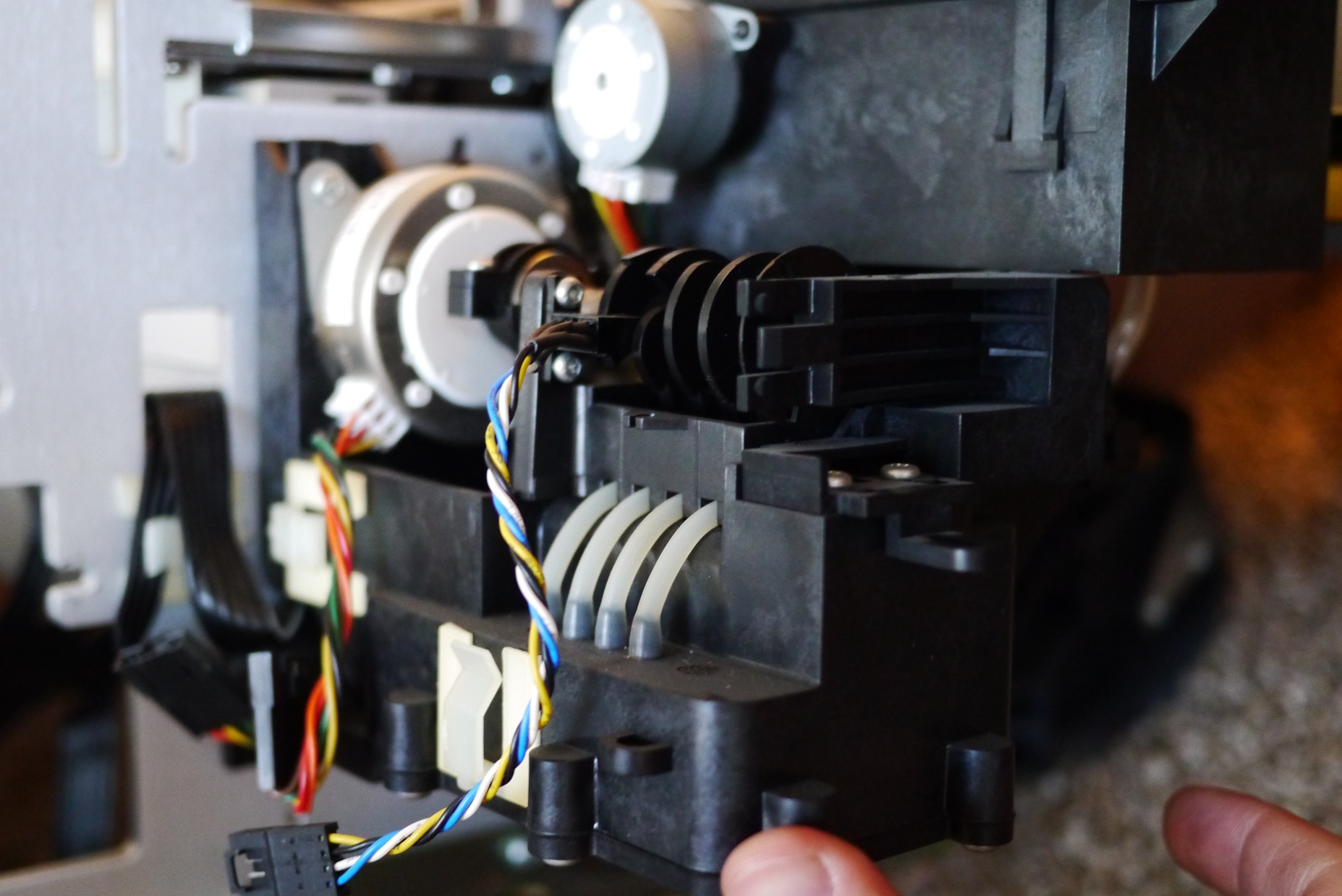
This module has two parts, on the left a crankshaft operates a small vacuum pump, on the right a set of pinch valves isolate individual vacuum lines. A clever bit of design is the use of a spring to utilize the motion of one stepper motor for two jobs.
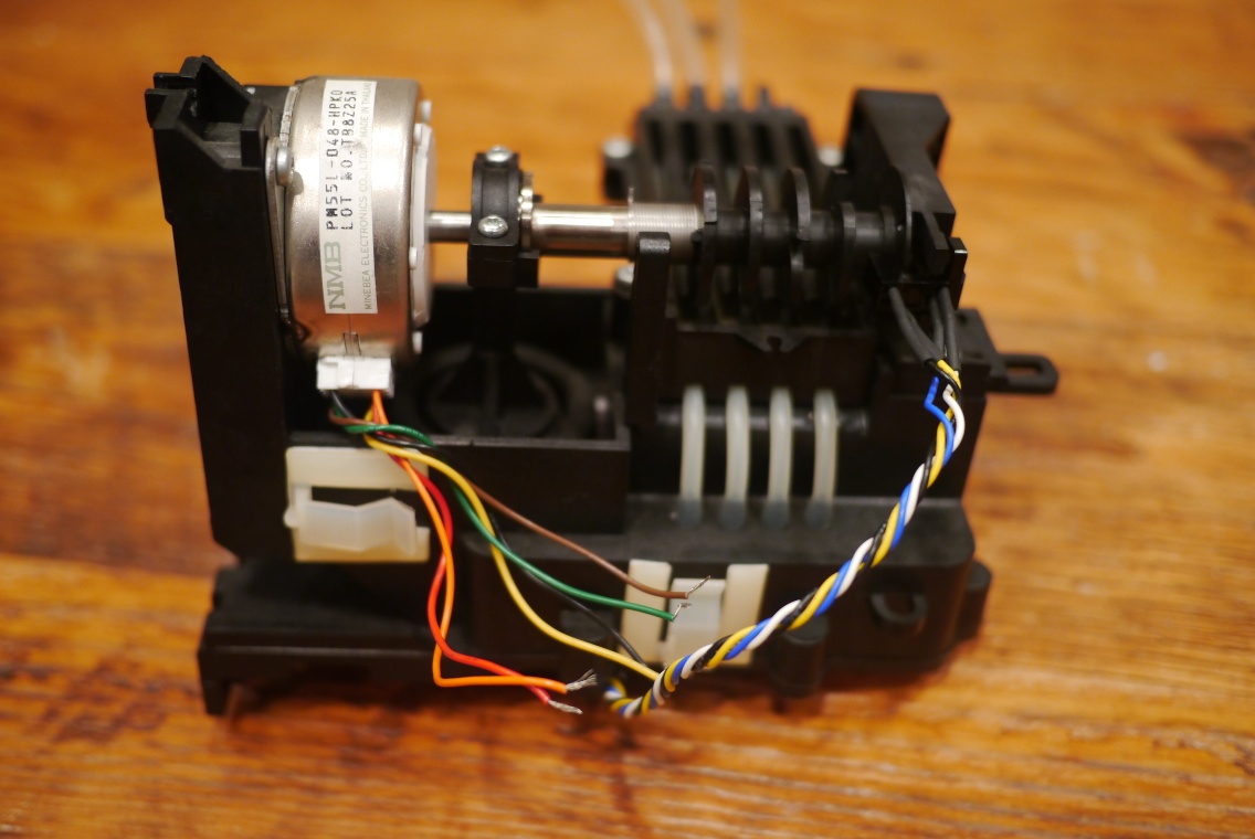
The spring is acting as a one way bearing. One way bearings will lock against a shaft and rotate when spun one direction, but spun the opposite way and they will free wheel. When the stepper motor rotates clockwise it spins freely inside the spring, the vacuum selector on the right does not move, but the vacuum piston on the left is cycled up and down, creating a vacuum. When the stepper rotates counter-clockwise the spring tightens around the shaft and the vacuum selector shaft rotates. As it rotates, one by one cams will pinch off all but one of the lines. This allows the vacuum to operate on a single print head color at a time. The vacuum created by the pump must be too small to pump against all 4 print heads at one time.
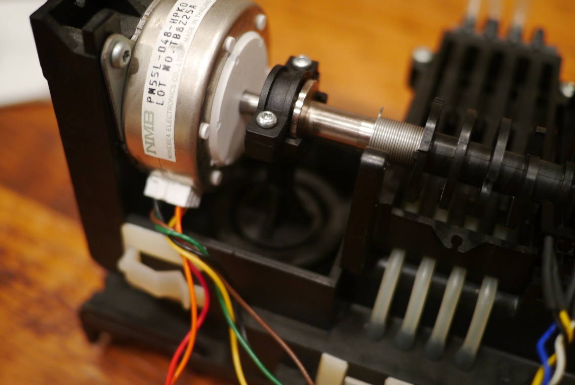
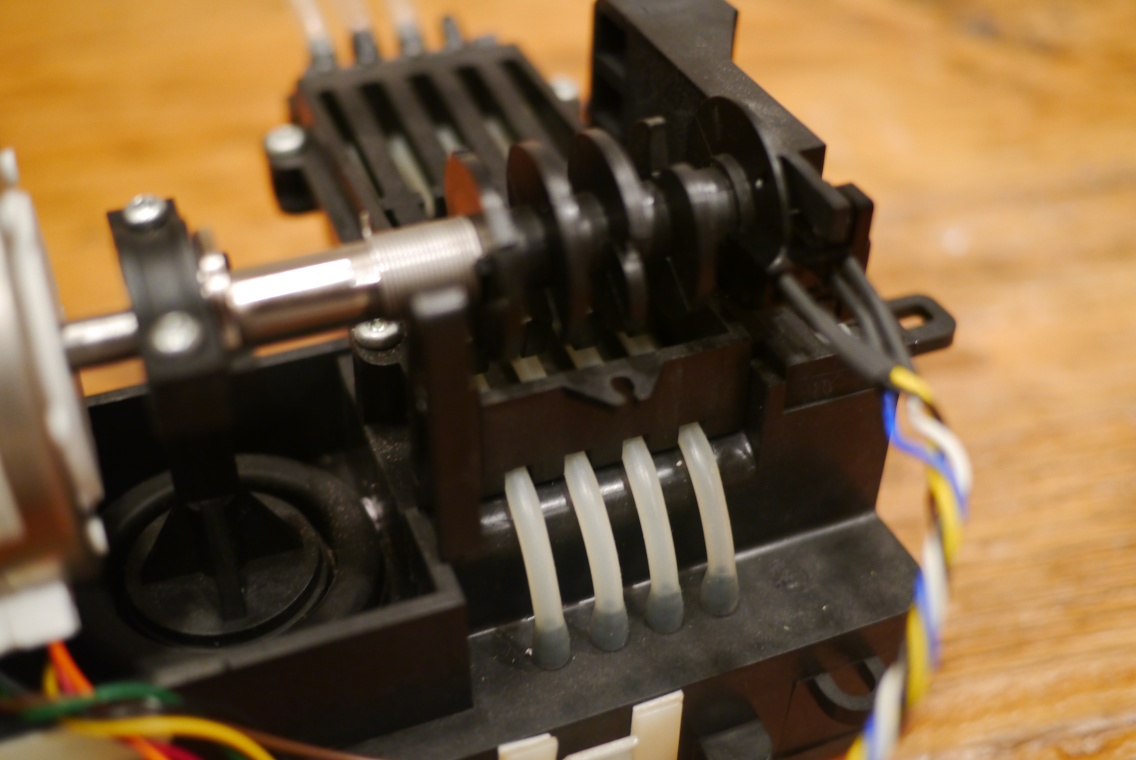 The optical switch on the right (white, blue, yellow and brown wires) and a slotted disk on the selector switch tell the printer which line is currently being pinched.
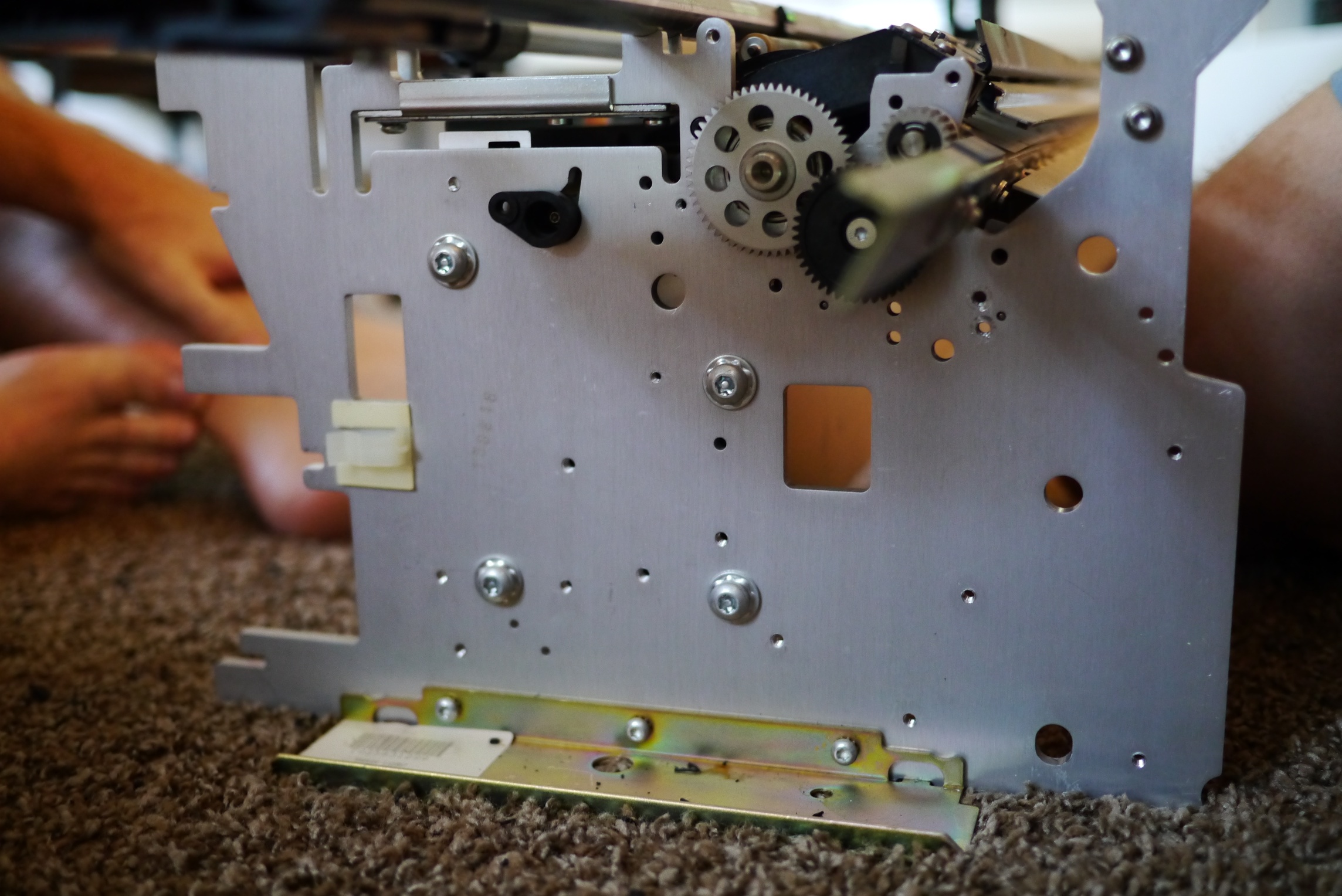
Moving around to the other side, the main paper feed roller is driven by a pretty large servo motor with attached encoder.

The main frame of the plotter is made from a massive aluminum extrusion and thick end plates.
That’s it for the disassembly, here’s the parts I saved.
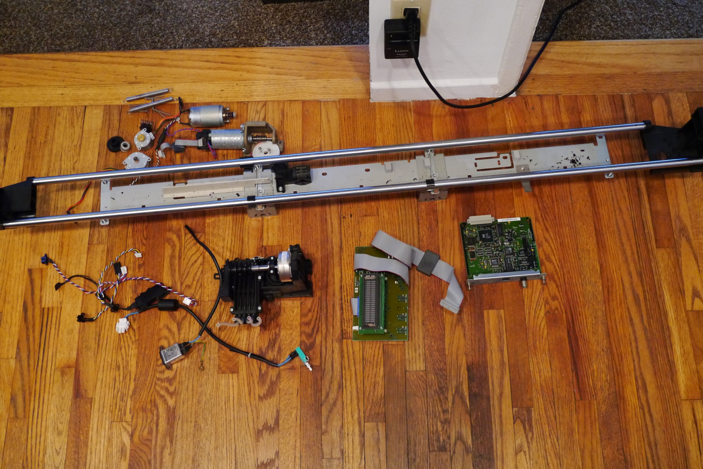
Final part count:
- 1 set of linear rails
- 4 Omron optical switches
- 1 DC motor with attached encoder
- 1 plain DC motor
- 3 stepper motors
- 1 vacuum assembly
- 1 power entry module with switch
- 1 samsung VFD
- Various springs
- Large heat sink with gap pad and IC clips (not pictured)
These parts will get stored until the right project comes along. I think the rails and DC motor would actually make a good basis for a motorized time lapse camera rig.
