One of the first steps in reverse engineering a product is understanding how it works. Ideally I would have access to the actual mold-a-rama (MAR), however they are rare and expensive. I could find an operating installation, but the closest operating MAR is at a zoo several hours away. I also have been unable to find pictures or video of the mechanics below the cabinet. The only parts visible from the images I’ve seen are the molds, mold rams, and ejector. All the complicated bits are hidden from view in the cabinet. The last avenue is products documentation in the form of manuals and patents. Fortunately I am an awesome google-er and have found both. The operation and repair manual can be found here:
http://www.scribd.com/doc/37301298?secret_password=1ehb8rphnat7ykzt6zu3
MAR machines use a process called gas-assist injection molding, a hybrid process somewhere between blow molding and injection molding. In traditional injection molding, usually resulting in solid objects, a small amount of plastic is injected into a mold where it cools completely and then is ejected. In blow molding, resulting in hollow objects, a tube of semi-molten plastic is clamped between mold halves at which point air is used to push the plastic against the mold. I’ll go into detail on the method the MAR uses a little later. The designers probably used gas-assist as it speeds up the cooling time of the plastic ultimately reducing the cycle time to around a minute. If traditional methods had been used the figurine would have been very small (lame) or the cooling time very long (>5 min). Seeing as this was basically a kids attraction at museums, theme parks and zoos you’re going to have a hard time getting kids to wait around 5 minutes to get their toy.
The manual describes the components, layout, and operation of the major subsystems.
Mold-a-rama subsystems:
- Hydraulics
- pump and motor
- reservoir
- lines
- rams
- valves
- hydraulic fluid (oil)
- Pneumatics
- air compressor
- valves
- air tank
- Cooling system
- refrigeration unit
- heat exchanger
- water pump
- water reservoir
- Plastic system
- Melting pot
- pellet hopper
- injection ram
- air ram
- air/plastic valve
- Electronics
- rotary actuator
- solenoids
- power supply
Missing from the service manual are descriptions of the actual injection molding components. This is the most important part of the system to understand if I am going to recreate the MAR. Fortunately I found the original patent, US3068518.
http://www.google.com/patents/about?id=R0hgAAAAEBAJ&dq=3068518
It’s written in typical patent verbiage, meaning you have to reread everything a few times to understand it. The relevent part to me are the drawings and specific descriptions. The basic operation goes like this:
- mold halves close
- molten plastic is injected into the mold cavity.
- air is blown into the mold to remove excess plastic
- Cold water is circulated in the mold halves
- mold halves open
- ram ejects plastic figure.
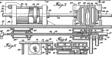
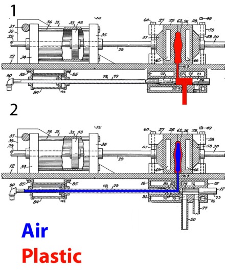
The heart of the machine is the valve which controls the flow of plastic and air into the mold, lower right number 15 below.
Basically by using a sliding bar (17) that alternately blocks the plastic inlet (75) and the air inlet (81) The mold is filled then cleared.
Here’s how the valve works.
Rod 78 functions as both a pipe to transfer air to the mold and an actuator to move valve 17 to the first and second position. In position 1 the valve is pushed to the left, which allows plastic to flow into the mold. After the mold has been filled completely piston 84 and valve 17 move to the right, position 2, closing off the plastic fill port and opening port 81 which fills the mold cavity with air.
The next diagram illustrates the filling process.
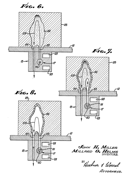
 In figure 6 you can see the two holes in the bottom surface of the mold that do the filling. 63 is the entrance and 64 is the exit. Plastic is pumped in to completely fill the mold, to the point that the excess flow out 63. During this time chilled ~40 degree water is pumped into the mold halves to cool a thin layer of plastic to the inside of the mold. The cylindrical valve(17) then slides over covering the plastic fill port and revealing the air fill port, blowing air into the mold shooting the un-cooled plastic out the exit port (64).
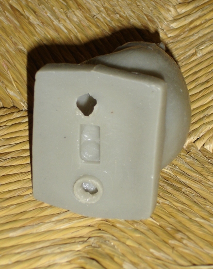
If you look at the bottom of mold-a-rama figurines you can see the remains of the two ports.
Some general notes on the operation:
- The plastic/air control valve (15) is heated to prevent liquid plastic from cooling and jamming the moveable valve.
- A freon based refrigeration system is used to cool the water, via a heat exchanger, that goes to the mold halves. This is loud, expensive, and large. I will replace this with solid-state peltier cooling if possible.
- The mold-a-rama does not run on a continuous basis, like say an injection molding machine in a factory, rather is operates sporadically throughout the day, maybe 10 to 200 times a day, going minutes or even hours between cycles. As a result this alters the way the plastic is melted. Rather than using a heated screw auger to melt the plastic and force it into the mold, the mold-a-rama uses a heated pot filled with molten plastic at all times. When the machine is run plastic is pumped from the pot into the mold. I’m debating where or not to use the MAR design in my implementation or the traditional screw auger setup as I dislike the idea of having to continually heat a pot of 250 degree plastic at all times. It would be nice if I could heat the plastic on demand, but that may increase the cycle time.
- The most common media is polyethylene pellets (Tm = 250F). I found that earlier machines use a different plastic that is more like a brittle wax, susceptible to melting if you left your toy in your car on a hot day. I may play with the idea of using paraffin wax (Tm = 120F) instead of plastic as a proof of concept. The much lower melting temperature and re-usability would be useful during the prototype phase.
- The patent shows a submersible motor and pump to transfer the molten plastic from the pot to the valve and eventually to the mold. It’s clear that the original manufacturer changed this for the production machines, probably realizing that motors and pumps sitting in a tub of 250 degree molten plastic is not great for pump/motor life. They appear to have switched from a motor and pump to using a hydraulic piston to transfer the plastic. This is still somewhat of an unknown, I need to research how you can use a piston to transfer the molten plastic from the pot to the valve.
- In the patent they show a large pot. I found that they switched to a smaller pot and a refill hopper for the final design. The small pot has a float that senses the level of the molten plastic. When the level gets too low a motor is activated that turns a screw auger to transfer pellets from the hopper to the pot. While the motor is turning the auger it also turns a paddle in the heated pot to ensure the pellet are incorporated into the molten plastic.
- The pot and valve are heated using electric heater elements, not the steam heater in the patent.
- Being designed in in the 50’s, the electronic control system is entirely analog. A slowly rotating motor turns a shaft with cams at different angles which in turn activate switches. This has got to be a pain to work with, so I’m going to replace it with a microcontroller.


great job, just saved me a bunch of time. did you ever do anything with all this knowledge?
I am building a smaller scale replica of the original Mold-A-Rama. See newer post on this blog.
I was recommended this web site via my cousin. I’m no longer positive whether or not this post is
written through him as nobody else realize such certain approximately
my problem. You are wonderful! Thank you!
Pingback: general design discussion • Re: Examples of good/clean design using rotomold? Does it ex | Grabber